556 clock problem

foTONICS

Sep 30, 2011
332
Joined
Sep 30, 2011
Messages
332
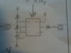
I have a 556 timer set up to produce two different square waves (1Hz and 10kHz). The 1Hz signal coming off of pin 9 works correctly, but the 10kHz coming off of pin 5 just shows a steady 5V. I checked the voltage divider going into pin 1 (which controls the 10kHz) and it shows 5V.

The voltage divider is two 4.7k ohm resistors so I should see 2.5V right? I'm just wondering if a burnt out resistor would cancel out the voltage divider and not allow the capacitor to discharge. Am I on the right track here?
 

KJ6EAD

Aug 13, 2011
1,114
Joined
Aug 13, 2011
Messages
1,114
What voltage divider? There usually isn't one in this type of circuit. Are you referring to the charge/discharge timing resistors? Show your schematic.
 
Last edited:

davenn

Moderator
Sep 5, 2009
14,470
Joined
Sep 5, 2009
Messages
14,470
moved to a more appropriate section of the forum :)

cheers
Dave
 

foTONICS

Sep 30, 2011
332
Joined
Sep 30, 2011
Messages
332
This is not a circuit I am building but one I'm repairing. The voltage divider was just to supply pin 1 with 2.5V from a supply of 5V. The pic is a little fuzzy but the two resistors on the left are 4.7k ohms and the cap is a 0.01uF. The pins , clock wise starting from the top left, are 1; 6; 2; 3; 5; and 4.

I guess my question is that if the discharge gets double the voltage that was intended would that be the reason why the output just stays at a steady 5V?

At first I did the easy fix and just replaced the 556 but the new one does the same thing
 

Attachments

  • 581071_3968119362146_1255296827_3567766_915393284_n.jpg
    581071_3968119362146_1255296827_3567766_915393284_n.jpg
    74.5 KB · Views: 109

KJ6EAD

Aug 13, 2011
1,114
Joined
Aug 13, 2011
Messages
1,114
The supply is on pin 14, not 1 and it's 5V. The 556 is not designed to operate from a supply less than 4.5V. The configuration shown in your fuzzy picture is a typical astable for a 555. You need to look at the data sheet (link below) for the 556 to get the pin numbers straight. Two 4.7k resistors and a 10nF (0.01μF) are correct for ~10kHz operation.

http://www.ti.com/litv/pdf/snas549
 
Last edited:

foTONICS

Sep 30, 2011
332
Joined
Sep 30, 2011
Messages
332
When I said supply pin 1 with 2.5V I was referring to the discharge A pin not the power supply for the entire chip. pin 1 is getting it's voltage from in between the two 4.7k resistors. So in theory it should be 2.5V pin 1 is receiving right?
 

timothy48342

Nov 28, 2011
218
Joined
Nov 28, 2011
Messages
218
Nope, not 2.5V between the 2 resistors. (well, there might be 2.5V there briefly when the power is first turned on.)
When the discharge pin is not drawing current, the cap fills from current through the "voltage divider", but as this happens the voltage across the cap increases. For instance when it is at 1V, the point between the 2 resistors will be at 3V. (Halfway between 1V and 5V)
When the voltage on the threashold pin (thats the same node as discharge and the middle of the 2 resistors) then the 555 changes state and the discharge pin draws current.
edit: Opps. It's actually the voltage on the trigger pin that cause it to respond to the raising voltage:endEdit
Both resistors feed the discharge pin. As this happens the voltage across the cap drops and so does that middle node, which again... is also the threashold pin. When the voltage drops far enough, the 555 chages state again and we do it all over.
-tim
edit2:I don't think you have it hooked up the way I thought you did, so that may all be wrong. Can you post a better pic?:endEdit2
edit3:Oh, I see now. Everything I said about both resistors feeding the discharge pin when it draws current was ok, but I see that the threashold and trigger connect directly to the cap. There voltage still rises and falls as the cap fills and drains.:endEdit3
 
Last edited:

duke37

Jan 9, 2011
5,364
Joined
Jan 9, 2011
Messages
5,364
Just a thought, how are you measuring the output voltage?
What is the supply voltage?
If the voltage is varying at 10kHz, a slow meter will measure the average voltage.
 

foTONICS

Sep 30, 2011
332
Joined
Sep 30, 2011
Messages
332
The supply is a steady 5V fed in from a fixed power supply.

I'm measuring the output with a tektronics oscilloscope and a 1:1 probe
 

foTONICS

Sep 30, 2011
332
Joined
Sep 30, 2011
Messages
332
I also want to mention that I work at a school. There are about 50 other boards with this same setup and they all work so I've narrowed it down to a defective component, I just don't know which one
 

duke37

Jan 9, 2011
5,364
Joined
Jan 9, 2011
Messages
5,364
From what I remember, the 555 (so 556) is an invertor. If the output is high, then, the trigger/threshold will be low. Measure this voltage and discharge to see if they are low.
Is there a short to ground?
What is the method of construction?
 

foTONICS

Sep 30, 2011
332
Joined
Sep 30, 2011
Messages
332
I replaced the two 4.7k resistors and the cap and now the 10kHz pulse works, but now the 1Hz is gone

side note, is it okay to replace SMD components with equivelant thru hole components?
 

(*steve*)

¡sǝpodᴉʇuɐ ǝɥʇ ɹɐǝɥd
Moderator
Jan 21, 2010
25,510
Joined
Jan 21, 2010
Messages
25,510
I replaced the two 4.7k resistors and the cap and now the 10kHz pulse works, but now the 1Hz is gone

Sounds like you have some interaction between the two circuits that you don't want.

Have you posted a schematic?

side note, is it okay to replace SMD components with equivelant thru hole components?

Outside of really high frequency stuff where lead length matters, it's just a case of physical size and connecting the leads in the right places -- no issue if you can fit them in.
 

foTONICS

Sep 30, 2011
332
Joined
Sep 30, 2011
Messages
332
Have you posted a schematic?

I took a extremely blurry picture and posted it on the first page. I used an iPod as I don't have a camera so if I zoomed out to capture the entire schematic you wouldn't be able to see a thing. The setup is exactly the same for the other side of the 556 just with different values to obtain the 1Hz.

Since the voltage wasn't changing I blamed the discharge of the capacitor so I replaced it along with the two resistors with thru hole components and that got everything working. I cannot find any more SMD components with those values so I may just replace that side of the chip with thru hole components as well.

The whole board is about 12 inches long, 6 inches wide, and about 1 1/2 inches thick so I have plenty of room for thru hole stuff. I just bent the leads in a zig zag pattern to keep the stuff from hitting any traces

I noticed that at some point someone came in and added a smoothing cap across the
+ and Gnd that wasnt on the schematic. Would this be to stop the 10kHz from interfering from the 1Hz or just to keep the 556 from affecting other devices?
 

foTONICS

Sep 30, 2011
332
Joined
Sep 30, 2011
Messages
332
Outside of really high frequency stuff where lead length matters, it's just a case of physical size and connecting the leads in the right places -- no issue if you can fit them in.

you're talking about radio and microwave stuff right?
 

KJ6EAD

Aug 13, 2011
1,114
Joined
Aug 13, 2011
Messages
1,114
I noticed that at some point someone came in and added a smoothing cap across the + and Gnd that wasnt on the schematic. Would this be to stop the 10kHz from interfering from the 1Hz or just to keep the 556 from affecting other devices?

Both. See page 10 of the 555 datasheet under "Additional Information".
 
Last edited:

foTONICS

Sep 30, 2011
332
Joined
Sep 30, 2011
Messages
332
ya when i was building am/fm transmitters it was crazy seeing on the scope what an extra loop of wire would do to my signal
 
Top