Airwick Freshmatic Max unit

spike1947

Feb 4, 2016
68
Joined
Feb 4, 2016
Messages
68
Hi
I have a couple of Airwick Freshmatic Max Auto room spraying units , the have 3 settings on them I=9 minutes , II=18 Min and III=32 min .
I would like to change the time settings to spray every 60 Mins or there about's etc .
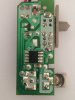
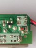
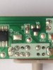
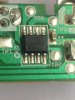
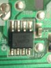
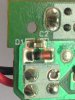
Is there anything I can make up to do that , or is there any module that I can fit , will post some pics of the Board later today , I don't have a Schematic for the board , will try draw something .
Just saying it now without the pics etc in case someone on here already knows about them ! .

Cheers

Spike
 

spike1947

Feb 4, 2016
68
Joined
Feb 4, 2016
Messages
68
Hi
Thanks for your reply , have seen that vid , good one but it is not addressing the time sequence for the bursts , I need some mod to have the sequence time gap much larger than it has ie , the longest is 32 mins , far to frequent ,would like it to spray hourly ! .

cheers

Spike
 

Attachments

  • upload_2018-3-3_8-18-4.png
    upload_2018-3-3_8-18-4.png
    700 bytes · Views: 143

KJ6EAD

Aug 13, 2011
1,114
Joined
Aug 13, 2011
Messages
1,114
Your upload is not good. Only a 700 byte thumbnail appears!

It's likely your device uses a COB circuit like the one Clive showed. If it has an exposed timing capacitor or resistor, you could replace one or both to affect the modification you desire, otherwise you'll have to replace the entire control board with a custom one.
 
Last edited:

spike1947

Feb 4, 2016
68
Joined
Feb 4, 2016
Messages
68
Hi
Thanks for your reply , have seen that vid , good one but it is not addressing the time sequence for the bursts , I need some mod to have the sequence time gap much larger than it has ie , the longest is 32 mins , far to frequent ,would like it to spray hourly ! .

cheers

Spike
Hi
It is only part of the quote from Kellys_eye .
 

73's de Edd

Aug 21, 2015
3,730
Joined
Aug 21, 2015
Messages
3,730
Sir spike1947 . . . . .

Considering that this is the board being found inside I see the COB, and to its right a monolithic multilayer ceramic
block capacitor ; which are inherently being limited in their max capacitance capability, versus physical size.
We might strongly assume . . . what else can we do ? . . . . . that this cap will be associated with the C factor of the RC time constants of an oscillator that gets digitally divided down in order to get your 9---18---32 min time periods.
With those three periods probably being altered by tapping in to alter the number of frequency divisions.

TRY THIS:

Figuring . . .actually, KNOWING . . . that if we make C larger in capacitance value, that would effectively make the timing period longer.

Set the unit beside you and reset to the shortest time of 9 minutes, so that it will shoot you right in the face if using the dead time to watch TV, etc. Start timing after that to see exactly long I cycle lasts and hits you again.
Info is now in hand.

So let's get a polypropylene / polyeth / or / paper 1 ufd capacitor with long leads so that we can FRESHLY tin both leads . . . up to their shiny chrome plated appearance . . . . and then do a QUICK solder tack of the two leads, to the two respective side tabs of the mini ceramic cap.
Then you do the retiming to see if the period is being longer this test time.
If being a longer time the capacitor needs to be proportionally larger in capacitance to stretch out to your desired longer timing period.
BUT . . . . . you need to see what the 32 min period NOW tests out as, since that one is for altering to a 1 hr period..

VIS-U-REFERENCING . . . . .
upload_2018-3-3_4-47-55.png

73's de Edd
.....
 
Last edited:

spike1947

Feb 4, 2016
68
Joined
Feb 4, 2016
Messages
68
OK , that is not the same board as in my Airwick Freshmatic MAX , attached pics .
 

Attachments

  • IMG_0806.JPG
    IMG_0806.JPG
    244.7 KB · Views: 153
  • IMG_0809.JPG
    IMG_0809.JPG
    200.5 KB · Views: 154
  • IMG_0810.JPG
    IMG_0810.JPG
    211.8 KB · Views: 141
  • IMG_0812.JPG
    IMG_0812.JPG
    220.9 KB · Views: 140
  • IMG_0813.JPG
    IMG_0813.JPG
    212 KB · Views: 133
  • IMG_0814.JPG
    IMG_0814.JPG
    225.3 KB · Views: 140

73's de Edd

Aug 21, 2015
3,730
Joined
Aug 21, 2015
Messages
3,730
Looks like you got a real encapsulated and leaded chip on your board, not the naked chip covered with an epoxy blob . . . .continue test as suggested before . . .with C1 cap in your sights..
Conjunct thought . . . .
If you had a scope and freq counter / E-PUT, an analysis of TP1 should reveal it to be a production test point to permit instant timing evaluation . . . . vice . . . . your having to wait out your minimal 9 minutes.
 
Last edited:

KJ6EAD

Aug 13, 2011
1,114
Joined
Aug 13, 2011
Messages
1,114
I'd try to measure the capacitance of C1, then piggyback a second capacitor of same size and capacitance beside it, effectively doubling the value and hopefully the time period of all settings.

If that doesn't work, you would need to program your own PIC chip and install it.
 
Last edited:

kellys_eye

Jun 25, 2010
6,512
Joined
Jun 25, 2010
Messages
6,512
Anyone found a datasheet for the chip yet? No luck here :(

There will be an RC component pair that sets the chip clock and thus the timing - as mentioned already but a datasheet would make this fairly easy to do as the component values for the clock timing would be noted therein.
 

BobK

Jan 5, 2010
7,682
Joined
Jan 5, 2010
Messages
7,682
I doubt that that is a timing cap. More likely decoupling. All the micros I have used have an internal clock and do not need an external R and C.

Can anyone read the markings on the chip?

Bob
 

spike1947

Feb 4, 2016
68
Joined
Feb 4, 2016
Messages
68
I doubt that that is a timing cap. More likely decoupling. All the micros I have used have an internal clock and do not need an external R and C.

Can anyone read the markings on the chip?

Bob

Chip : RB 1401C , SAG 3C3
 

spike1947

Feb 4, 2016
68
Joined
Feb 4, 2016
Messages
68
Hi
I am thinking of removing the board and putting some timer in its place , does anyone have any idea's ! .

cheers
spike
 

kellys_eye

Jun 25, 2010
6,512
Joined
Jun 25, 2010
Messages
6,512
Depends on how you want it to operate. You can throw in a cheap digital timer module and set whatever time/date on it you want. All you need is a set of closing contacts to get power to the mechanism (I believe it's a rotating operation?).

But getting it to remain battery-powered and low consumption may be a little more involved.
 
Top