I don't know how old you are, or how long you have been interested in electronics, or what your current skills are, but no one follows the path you have chosen without learning some new skills. Entering a dialog with other EP members, in addition to resources you find on the Internet, is a good way to build on your knowledge and learn new skills.
It is unfortunate that your digital panel meters can measure only one polarity of input voltage with respect to power supply and signal commons, which are internally connected together by design. This particular design is less expensive to produce than a meter that reads inputs of either positive or negative polarity with respect to signal common. One solution to your problem is to full-wave rectify the DC signal before applying it to the meter, after low-pass RC filtering to remove the PWM pulses. That will allow the meter to read a motor drive signal that is either direction. Unfortunately, the circuit does not provide polarity indication of the input signal. If you need to display polarity, more circuitry is needed.
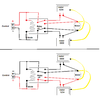
Building an accurate full-wave rectifier circuit may be beyond your current skill level, but I suggest that you at least try to do so. It generally requires the use of two operational amplifiers which can be dual op-amps in a common package. Usually two power supply rails, one positive and one negative with respect to power supply common are required, but some circuits can be used with a single positive supply rail if a special op-amp is also used. Most circuits require at least one small-signal diode (1N914, 1N4148, etc.) and sometimes two, as shown in the circuit below.
Almost any general-purpose op-amp will work, but the resistors values should be closely matched for a symmetrical output.