[Amplifier][13,56 Mhz][ ~ 15 dB] Transistor IRFD110 - does it work?

Anon_SD

Feb 8, 2014
24
Joined
Feb 8, 2014
Messages
24
Hi ppl,

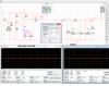
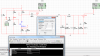
I designed an amplifier on multisim, I get 15 dB gain at 13,56 Mhz,
I want to connect an antenna at "vout" pin

but I don't know if the transistor is saturated or not, as I don't understand datasheet and i'm not good at all about circuits.
So I don't know if it will work in real or not..

If some of you have multisim i give you my schematics : https://www.dropbox.com/s/iqp6y4apgylcl9u/IRFD110 15dB circuit.ms13 ,
for others I took a pic : https://www.dropbox.com/s/0vb4clwpnpf1eeo/ampli.png

Thanks for some help about this problem, but if you found an other issue with your expérience I will listen to you ;)

I forgot tell you that my transistor is IRFD110 like this :
http://www.vishay.com/docs/91127/sihfd110.pdf
 
Last edited:

Harald Kapp

Moderator
Moderator
Nov 17, 2011
14,271
Joined
Nov 17, 2011
Messages
14,271
The IRFD110 is a switching transistor. It is probably not good at amplifying analog signals (I suppose your function generator is set to sine waves). Look at the output signal and watch for distortions.
Also check the power loss in the transistor. I don't know whether multisim has an option for this. If not, calculate RMS(Ids*Vds), that should give a sufficiently good approximation. Since the package is not designed for additional ccoling mechanisms, you need to keep the power loss small so the transistor can't overheat. The transistor has a thermal resistance Rthja=120 K/W. The max. junction temperature is 175 °C. Assuming an ambient temperature of 30 °C, that leaves 145 ° for the temperature gradient across the package. 130 °/ 120 K/W = 1.08W. This is a bit less than the max. 1.3 W stated in the datasheet and will become worse if ambient temperature rises above 30 °C.
 

duke37

Jan 9, 2011
5,364
Joined
Jan 9, 2011
Messages
5,364
What does D1 do?
Is it the wrong way round?
Does the Multisim transistor model include capacitances?
 

Anon_SD

Feb 8, 2014
24
Joined
Feb 8, 2014
Messages
24
Thanks for answering,
I put D1 by error :( , but I just see that I need it for getting the gain I need..

I never saw a diode like that, I don't think i can let it..

That means I have to re design it

Ok Harald I will look into the power loss, if I understand it has to be inferior to 1.08 W.

Duke, I asked your question about capacitances and I will tell you about when I know more
 
Last edited:

Harald Kapp

Moderator
Moderator
Nov 17, 2011
14,271
Joined
Nov 17, 2011
Messages
14,271
Sorry, I've been in a bit of a hurry this morning.

There's one more issue with this circuit: The IRFD110 is an enhancement MOSFET. TThis means that it requires Vgs> Vgsth (2V...4V, with this large spread, yes, see datasheet) to become conducting. Your generator is set up for a sine of +-5V. The transistor will be off for Vin<Vgsth and therefore can amplify only the portion of the signal >Vgsth.

To overcome this, you need to:
- bias the transistor with a DC voltage to bring it into the linear operating range.
- add some negative feedback to stabilize the circuit and to account for the variance in Vgsth. If you look at the output with a "scope" you will see the distorted signal.

Here is a basic text about MOSFET amplifiers in common source configuration.
 

Anon_SD

Feb 8, 2014
24
Joined
Feb 8, 2014
Messages
24
Thanks,

my input comes from an electronic cards which produces a 0 - 5 V signal

So do you mean that it can't work when my input signal is inferior < 2 to 4 volts ?

I verified that Id < 1 A and Vds < 100 V for avoiding saturation
 

Anon_SD

Feb 8, 2014
24
Joined
Feb 8, 2014
Messages
24
I think all my schematic is wrong ><

the part after the transistor is a filter for 13,56 Mhz
 

Harald Kapp

Moderator
Moderator
Nov 17, 2011
14,271
Joined
Nov 17, 2011
Messages
14,271
Use this as a starting point:
attachment.php


I don't have Multisim, I use LTSPICE. I used another transistor because I didn't have a model of teh IRFD110 at hand.

Tweak this circuit for your requirements.
 

Attachments

  • 13mhz.jpg
    13mhz.jpg
    136.2 KB · Views: 733

Anon_SD

Feb 8, 2014
24
Joined
Feb 8, 2014
Messages
24
Thanks a lot,

I did it with the right transistor, I got the same thing than you

small signal is vin

bigger is vout

I see now the problem when you talked about "distortion", indeed if I set input to 0- 5V
I can see them
 

Attachments

  • simu IRFD110.png
    simu IRFD110.png
    114.5 KB · Views: 260

Anon_SD

Feb 8, 2014
24
Joined
Feb 8, 2014
Messages
24
Is there a way to be able to set in input a 0 - 5V signal ?
Because I'm not able to amplify voltages superior to 0,4 V (in input)


I'm here now, in "simu" file vin is the "cleaner" signal,
"vinter" is just before my MHz filter, there is slight distortion,
but as you can see VIN amplitude is 5 V, and vinter is 5V too..i'm not able to amplify vinter when input is above 0,4 V...

Do you know the answer for that ?
I don't understand how "vout" can be so "huge" as vinter is as big as "vin" !!
But if it's "normal" so i will let it like that because it's what I want..

BTW I did a bias point analysis, in the board, first there is VDS = 4,25 V which I think is good according to graphs in datasheet.
then VGS = -4 V, I don't know if it's right ... I think not according to graphs in IRFD110 datasheet (no vgs < 0)
then ID = 85 mA, it's inferior to 1A so I think it's ok.

if some are interested i let you my schematic :
https://www.dropbox.com/s/bxuymqutk6p374y/IRFD110 design 13.56 Mhz.ms13

Thanks for you help :p

xoxo
 

Attachments

  • simu.png
    simu.png
    153.3 KB · Views: 203
  • bias point.png
    bias point.png
    106.5 KB · Views: 199

Harald Kapp

Moderator
Moderator
Nov 17, 2011
14,271
Joined
Nov 17, 2011
Messages
14,271
Is there a way to be able to set in input a 0 - 5V signal ?
Because I'm not able to amplify voltages superior to 0,4 V (in input)

You can design the amplifier for larger input signal. That's going to need a few more components. This simple circuit alone will probably not suffice.
One simple way is to use a resistive divider to reduce the input from 5V tp 0.4V, then amplify it. Workable, although a waste of signal quality.

I don't understand how "vout" can be so "huge" as vinter is as big as "vin" !!
This is probably due to resonances in the filter circuit. Give L2 a realistic series resistance and watch the output signal. Or tune the filter to another frequency.

VGS = -4 V, I don't know if it's right
No, it's not quite right. You got the sign wrong. What you see is V(4)-Vbias which is -Vgs, not Vgs.
 

Anon_SD

Feb 8, 2014
24
Joined
Feb 8, 2014
Messages
24
Thanks for your help,

i didn't see vgs was wrong :eek:

I didn't know that my resonnant circuit could give me a vout superior to its alimentation

Ok i will look how do it, thanks i will report my results ;)
 

Anon_SD

Feb 8, 2014
24
Joined
Feb 8, 2014
Messages
24
In order to get a large signal at output of my mosfet I had to increase from 12 V to 24V
the element V2 on your schematic, is it "normal" ?

I think yes but my little experience in circuit can't convince me

Thanks :)
 

Harald Kapp

Moderator
Moderator
Nov 17, 2011
14,271
Joined
Nov 17, 2011
Messages
14,271
V1 and V2 are voltage sources in LTSPICE.
V2 is the DC supply (12V in my circuit).
V1 is the sine generator (0.1 V).

In order to get a large signal at output of my mosfet I had to increase from 12 V to 24V
Waht do you mean by this statement? What amplitude of the output voltage do you need? Are you sure it is the supply voltage that limits the output signal, not the gain of the amplifier? You can tweak the gain by changing the source and drain resistors.
 

Anon_SD

Feb 8, 2014
24
Joined
Feb 8, 2014
Messages
24
Thanks,

Yes it's the supply voltage limits the output signal,
because when I change source and drain resistors I get so much distortion, so
I'm obliged to let them to 27 Ohms and 64 Ohms :/

The output I need is lead by my output gain of this amplifier which should be 15,5 dB
 

Anon_SD

Feb 8, 2014
24
Joined
Feb 8, 2014
Messages
24
edit .
 

Attachments

  • vin vout 3 k ohms NOT OK.png
    vin vout 3 k ohms NOT OK.png
    100.9 KB · Views: 188
  • vin vout 3 ohms OK.png
    vin vout 3 ohms OK.png
    109.2 KB · Views: 209
Last edited:

Anon_SD

Feb 8, 2014
24
Joined
Feb 8, 2014
Messages
24
I had a so wrong idea,
I don't need a voltage amplifier,
I need a current amplifier at 13,56 Mhz, I doon't know where start, maybe with a 2N2222?...

thanks xoxo
 

Harald Kapp

Moderator
Moderator
Nov 17, 2011
14,271
Joined
Nov 17, 2011
Messages
14,271
Sofia,
start with clearly expressing your requirements:
- what is your input signal?
- what is your output signal?
- what power supply is available?
- what other requirements may linger in the back?
 

Anon_SD

Feb 8, 2014
24
Joined
Feb 8, 2014
Messages
24
Ok,

so my input signal is a sinusoidal 13.56 Mhz, from 0 to 5V,
my input power is 0,200 W, and I need an output power of 7 - 8 Watts

the power supply can be from -24 to 24 (or -12/+12 etc..)

as my voltage is already high, my only option to increase the power is to increase the current.
I need a 2N2222 current amplifier circuit
That's why I did this schematic :
with P = U *I and U = R I, I guessed that my input current in real is 0,04 A,
and I need to multiply it by 40, in order to get minimum 200 mA in output of my circuit


but i'm not sure of the input thevenin/norton I tried them but I don't get the real input power of 200 mW.

And The output has only a power final very low (lower than input)

I don't know what is wrong here , as what I want to do is not very difficult :(

here are screens:

beginning of simulation :
power initial.png

end of simulation :
power final.png

and the bias point :
bias point.png
thanks a lot
 

Harald Kapp

Moderator
Moderator
Nov 17, 2011
14,271
Joined
Nov 17, 2011
Messages
14,271
and I need an output power of 7 - 8 Watts
What is the load? 8 W can be realised in many ways:
- high voltage, low current -> high load resistance
- low voltage, high current -> low load resistance

By the way: are you talking rms power or peak power?

as my voltage is already high, my only option to increase the power is to increase the current
Not so. Your input voltage is 5V, your supply voltage is up to +-24V, so there is room for voltage amplification, too.
You need to know the load resistance, then you can calculate current and voltage requirements from
I=sqrt(P/R) and/or
V=sqrt(P*R)

The input power to the amplifier is (comparatively) irrelvant. Also you can use either a BJT or a FET to create the necessary gain. Being able to deliver a high current to the output does not imply the use of a BJT.
At the power level you need (8W) a class A amplifier (your design) is probably not a very good choice as it will burn lots of power internally. Look into class B amplifiers.

At 13 Mhz an amplifier already becomes a bit tricky since parasitic effects have a good deal of influence on the behavior of the amplifier, especially its frequency response. Try to get a fundamental understanding of the operation of an amplifier before you go to 13 MHz. Here's a suitable tutorial.
 
Top