Can you help designing buffer?

Status
Not open for further replies.

sono

Jan 12, 2025
8
Joined
Jan 12, 2025
Messages
8
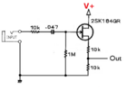
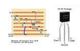
I would like to make this circuit on stripboard that you can see on the file attached. This is actually a buffer with some modification, so that the signal leaving the circuit is reduced with 50% in the end.

I wondered if someone could help me convert it to stripboard design? I cannot do that myself, my knowledge is too little for that.
 

Attachments

  • 55100.png
    55100.png
    45.6 KB · Views: 11

bertus

Moderator
Nov 8, 2019
3,837
Joined
Nov 8, 2019
Messages
3,837
Hello,

You could try to dwaw a setup in pebble:
You can choose between different sizes of stripboard.

Bertus
 

sono

Jan 12, 2025
8
Joined
Jan 12, 2025
Messages
8

I have seen these videos but I don't know how to insert certain components, if they need to be on a common stripe or not, for example. An also if there is more than 1 ground out, how to convert it on the board, like connecting them to make them 1 or leave them as is. If someone created it I could see it right away and could redo that myself in the future.
 

sono

Jan 12, 2025
8
Joined
Jan 12, 2025
Messages
8
If there was a video that shows whether components go to the same or different rails that would be helpful. So that would take routing examples from block diagrams and shew how that looks on the stripboard. The problem with most videos is that they show the conversion from beginning to end, but routing examples are scattered all along, not every routing situation is contained in ever video, so it is a kind of mess of information that is difficult to handle for a beginner like me. IF there was a video that only shows routing cases and how to make them on the stripboard that would be the best. I am not interested in choosing components from the list, etc. that is boring and I already know that.
 

sono

Jan 12, 2025
8
Joined
Jan 12, 2025
Messages
8
Okay, just to clarify, here is one that has a bunch of routing I have no clue about how to make on the stripboard:

Routing.JPG

I encircled with red which routing situations I am interested in. Can you link any video that shows examples to these routings only? And not to other things like selecting items in programs, setting their value, etc.
 

Martaine2005

May 12, 2015
5,277
Joined
May 12, 2015
Messages
5,277
You can use that exact diagram for the layout.
All strip board requires cutting traces so as not to cause short circuits. From the cut traces, a jumper wire is soldered to the next trace being used by a component leg.
 

Harald Kapp

Moderator
Moderator
Nov 17, 2011
14,273
Joined
Nov 17, 2011
Messages
14,273
Why would you use a buffer at all? The output impedance is rather high at 5 kOhm. You could achieve the same effect by simply using the resistive divider alone on the input signal. Assuming, of course, that the input swings between GND and Vcc.
 

poormystic

Jul 23, 2023
187
Joined
Jul 23, 2023
Messages
187
"Dead bug" designs have sometimes been potted in resins, to become quite durable. And irreparable.

Still, this is far from the OP's query.
I certainly hope they took Harald Kapp's advice seriously and didn't bother building the circuit.
How did it all go, Sono?
 
Last edited:

Delta Prime

Jul 29, 2020
2,987
Joined
Jul 29, 2020
Messages
2,987
Still, this is far from the OP's query.
True but things evolve, especially conversations of the OP query see here. :)
My comment stands “no school like the old school!”


Delta Prime

Jul 29, 2020
2,987
Joined
Jul 29, 2020
Messages
2,987
"Dead bug" designs have sometimes been potted in resins, to become quite durable. And irreparable
I employ that technique myself, depending on the potting material they can be heated and melted releasing the electronic components ,in my case curiosity on very clever designs with no documentation and encapsulated.
I have been quite successful & have learned a great deal from my exploits! I use those clever designs in my own circuits.
 
Last edited:

sono

Jan 12, 2025
8
Joined
Jan 12, 2025
Messages
8
"Dead bug" designs have sometimes been potted in resins, to become quite durable. And irreparable.

Still, this is far from the OP's query.
I certainly hope they took Harald Kapp's advice seriously and didn't bother building the circuit.
How did it all go, Sono?

in the end I chose this design and we'll see, I have some other versions, too. I am waiting for someone to solder it this month I have no precise soldering iron only one with large tip.
 

Attachments

  • 55100.png
    55100.png
    45.6 KB · Views: 3
  • Buffer.png
    Buffer.png
    216.6 KB · Views: 3

davenn

Moderator
Sep 5, 2009
14,471
Joined
Sep 5, 2009
Messages
14,471
Big cleanup

Deleted many off topic posts from several people

Thread closed
 
Status
Not open for further replies.
Top