prateeksikka,
To answer your question;
Class A the transistor conducts for the full cycle drawing a lot of current the efficiency <30%, but it's low noise and a good quality amplifier.
Class B the transistors are only on when a signal is present and draw no power when there's no signal, this is high noise because the transistor needs 0.7 to turn on crossover distortion occurs when the waveform goes near 0.7V but it's more efficient and it runs cool.
Class AB is a happy medium, the transistors are biased on with a very small current to keep their bases above 0.7V and get rid of any crossover distortion and keep the efficiency reasonable by only using a small current.
Class C is used only in RF amplifiers that don't rely on the amplitude of the signal to transmit information for example CW FM, FSK and PFM, its also used in some inverters. The transistor is only on for half the cycle and it's either switched on or off, capacitors and inductors in the output filter the harmonics and produce a sine wave, it's fairly noisy but can be 90% efficient.
Class D is fairly new and its used in high efficiency audio amplifiers. Like class C the transistor is only switched on and off but this is done at a high frequency and if PWM with the input signal. For example an audio amplifier with a bandwidth of 20kHz will require a switching frequency of >100kHz this is then connected to the load via a low pass filter made from inductors and capacitors. The result is a high efficiency audio amplifier but the main disadvantages are noise (some of it RF) and a complex circuit is required. This is improving all the time and you can now buy specialist IC for this purpose.
My question:
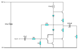
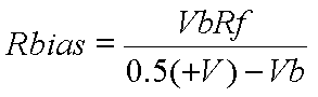
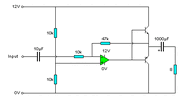
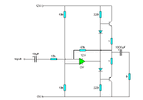
How do I calculate the value of Rbias in this class AB amplifier?
I thought it would be self biasing but the DC output level is far too low and this severely reduces the output drive capability.