DC MOTOR QUESTION

DiodeDave

Dec 7, 2011
46
Joined
Dec 7, 2011
Messages
46
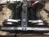
I have 2 24v DC permanent magnet motors wired in parallel to 2 12v marine batteries wired in series.

The motors are connected via gears to 2 axles which make up a truck for a 1/8 scale locomotive.

I don't think the truck has equal force on each axle. (The frame of the locomotive is lower in the front than in the back. I think this puts more pressure on the front axle than the rear. The rear axle slips while the front axle does not.)

My question: If the motors are wired in parallel, and one motor slips and runs faster than the other motor, which motor is using more current?

Thank you all.
 

Arouse1973

Adam
Dec 18, 2013
5,178
Joined
Dec 18, 2013
Messages
5,178
Hi Dave
The motor with the greatest load will draw the most current.
Adam
 

DiodeDave

Dec 7, 2011
46
Joined
Dec 7, 2011
Messages
46
Ok, forgive my lack of knowledge, but I thought electricity followed the path of least resistance. One motor was almost spinning freely, and the other was pulling the train. At one point, the motor with the load wasn't able to keep up. It should have had enough power and gearing to pull the train by itself.
 

Arouse1973

Adam
Dec 18, 2013
5,178
Joined
Dec 18, 2013
Messages
5,178
The faster the motor rotates the higher the back EMF. This is what reduces the current for an unloaded motor it basically has a lower effective voltage supplied to the coil. It like running the motor at a lower voltage.
Thanks
Adam
 

DiodeDave

Dec 7, 2011
46
Joined
Dec 7, 2011
Messages
46
Thank you Adam.

The slipping motor eventually overheated and started smoking. The fuse then blew. The motors ran for about 2 hours before the shut down. The non slipping motor was warm, but not hot. The other motor could not be touched.

The motors ran for about 2 hours. During the run, I noticed the train was slowing and had less power.

When I initially connected the batteries/controller/motors, I got a fault from my controller. It said there was either a motor or wiring short. After a few minutes, the fault stopped and I ran for 2 hours.

I think I have 2 separate issues. The design of my train, which put more pressure on one axle than the other and a motor issue.

Before running, one motor got warm while running on my bench.

What do you think?
 

Arouse1973

Adam
Dec 18, 2013
5,178
Joined
Dec 18, 2013
Messages
5,178
I think the slipping motor was getting hot because of friction, something maybe rubbing. When I used to race RC cars the coolest motor was always the one that was able to run out (Spin the fastest).
Adam
 

DiodeDave

Dec 7, 2011
46
Joined
Dec 7, 2011
Messages
46
Thank you so much for your help.

I ran for 2 hours yesterday a total of about 2 miles on our club train track. At the end of the run, my 60a fuse blew.

I put both motors on my bench tonight. And wired them individually.

The one which was cool at the end of the run and was the non slipping axle sounded normal (I shot a video of the motors running before the run).

The HOT motor sounds like a tooth is missing from a gear. It has a sealed gear box.

If both motors are wired in parallel, would the motor with the bad gear sap all of the current from the system leaving me with a slow running locomotive? ie the free running motor didn't take as much current?
 

Tha fios agaibh

Aug 11, 2014
2,253
Joined
Aug 11, 2014
Messages
2,253
Seems like one motor will always have more torque than the other. The rpm of the motors will vary and the gearbox will multiply the rpms making the imbalance between axles even greater. Seems like it'd be better to mechanically tie the axles together and use one big motor.
If the gearbox is overloading the motor, naturally, amperage will be higher. If the gearbox has a bad gear, it could also cause the motor to freewheel and cause less current to be drawn.

I would put a voltage meter at the motors so you can make sure your not running under voltage which will cause the amperage to jump up.

John
 

Windadct

May 25, 2011
25
Joined
May 25, 2011
Messages
25
First you have to realize you have motors with 2 "parallel" connections - one electrical and one mechanical. By hooking them up in parallel - they will not be perfectly matched from many perspectives ( Electrical performance, circuit connection, mechanical drag etc) -- So one motor will have a slightly higher torque than the other - and pull harder... what does this do to the other motor, it reduces the load - basically in this set up one motor stays a motor and the other resists the motion and becomes a generator. Now you have circulating power in the system - causing them to overheat. This is why you will not see this arrangement in engineered systems. 1/8 scale is not small - I would invest in DC drives with Master/slave capability so one will follow the other - the motor may also need some speed / shaft encoder to help regulate the two to make sure they are turning exactly the same speed. -- In reality this is not a trivial application.
 

BobK

Jan 5, 2010
7,682
Joined
Jan 5, 2010
Messages
7,682
I hate to ask this, but are the motors and gearing identical. Also, you might try swapping the two motors and see if the problem moves with the motor or stays with the axle.

Bob
 

Arouse1973

Adam
Dec 18, 2013
5,178
Joined
Dec 18, 2013
Messages
5,178
First you have to realize you have motors with 2 "parallel" connections - one electrical and one mechanical. By hooking them up in parallel - they will not be perfectly matched from many perspectives ( Electrical performance, circuit connection, mechanical drag etc) -- So one motor will have a slightly higher torque than the other - and pull harder... what does this do to the other motor, it reduces the load - basically in this set up one motor stays a motor and the other resists the motion and becomes a generator. Now you have circulating power in the system - causing them to overheat. This is why you will not see this arrangement in engineered systems. 1/8 scale is not small - I would invest in DC drives with Master/slave capability so one will follow the other - the motor may also need some speed / shaft encoder to help regulate the two to make sure they are turning exactly the same speed. -- In reality this is not a trivial application.

I thought the motors were on separate gearboxes? I am not sure I quite understand what you mean about the motor becoming a generator and circulating power in the system.
Thanks
Adam
 

Minder

Apr 24, 2015
3,561
Joined
Apr 24, 2015
Messages
3,561
It is never a good idea to mechanically link two motors especially where the differnce in load will vary without the use of electrical synchronization or some kind of electronic gearing in effect, this is not normally done in the motion control world.
As to generation, Any DC motor generates a BEMF that is the same polarity as the supplied power and the subsequent current is dependent on how close the generated DC is to the supplied DC.
The higher the load, the larger the difference, the higher the current.
M.
 

Arouse1973

Adam
Dec 18, 2013
5,178
Joined
Dec 18, 2013
Messages
5,178
Can we just clarify this Dave? "The motors are connected via gears to 2 axles" Do you have a separate gearbox and motor for each axel? What about a nice picture of the drive train, excuse the pun!
Adam
 

DiodeDave

Dec 7, 2011
46
Joined
Dec 7, 2011
Messages
46
The motors are each attached to a gear box. Each gear box is attached to a separate axle. As I was riding on Sunday, I could see the rear axle slipping. The locomotive did not have much power. The vendor said one axle should be able to pull 500 pounds. The loco, batteries, one gondola and my arse equal about 450 pounds. So I'm trying to determine why the axle with traction wasn't pulling me sufficiently.

The motor in the rear axle burnt up after 2 hours. Smoke, smell, blown fuse. I could feel the entire train slowing as the day progressed. The vendor thinks a magnet is loose.

But during the first 30 minutes or so, the rear axle slipped and I'm wondering if the power went to it (electricity follows the path of least resistance) or something else was going on.

I drove another train with a similar set up and pulled 800+ pounds around a mile long track.
 

Attachments

  • IMG_4532.JPG
    IMG_4532.JPG
    183.4 KB · Views: 103

Arouse1973

Adam
Dec 18, 2013
5,178
Joined
Dec 18, 2013
Messages
5,178
When you say slip, do you mean wheel spinning and not gearbox / clutch slipping? How fast do the wheels turn when off load?
 

DiodeDave

Dec 7, 2011
46
Joined
Dec 7, 2011
Messages
46
Slip as in the wheel slips on the rail. The motor/gear/axle are always in contact. No clutch in the setup. When the wheel is slipping (off load?) they are going faster than the train.

Usually the front axle was pulling and the rear would slip at time. I'm told this by an observer along the side of the track.
 

Arouse1973

Adam
Dec 18, 2013
5,178
Joined
Dec 18, 2013
Messages
5,178
Ok originally I thought the wheels might have been spinning as fast as they would of load. Thinking they might have been losing grip due to a weight imbalance. Now from what you have said I am thinking the motor is being overloaded by weight.

Thus the motor is generating as much torque as it can but is drawing too much current, this heats up the motors windings which in turn heats up the magnets.

The magnets lose magnetic flux as they get hot, this in turn reduces the back emf even further which increase the current and heat even further. Also heat will effect the expansion of metal parts like bearing, I guessing this could add to the problem.

That's my thought on it

Adam
 

Minder

Apr 24, 2015
3,561
Joined
Apr 24, 2015
Messages
3,561
It appears one motor cannot operate independent of the other which is the point I was making, Without wheel slip?
To take a leaf out of a full scale Loco.
There is a traction motor on each wheel and each has a synchronism via wheel slip detection.
Although each traction motor has a different G.B. they are not allowed to run at a independent rpm.
M.
 

DiodeDave

Dec 7, 2011
46
Joined
Dec 7, 2011
Messages
46
Here is what I think happened. Thanks to all for their patience and input. I started the day with the loco working fairly well. The rear wheels slipped some. I think it is because the wheels in the front truck are smaller diameter. This caused the rear wheels in the rear truck to have less downward force and therefore less friction and were more prone to slip.

I wondered how the electric power was being distributed. Now, I see the slipping wheels had less resistance and therefore the non slipping wheels took the current.

The motor which was slipping eventually started smoking. It eventually blew the 60a fuse. On my bench, it made a lot of noise and would not operate in reverse. I think 2 things were going on.

While it may have been slipping, it wasn't working freely and was slowing down the entire loco.

Now, I will try to equalize the downward force on the truck with the motors while the vendor is sending a replacement. (On July 6, I sent him an e mail telling him the motor got quite hot after one minute while running on my bench)
 
Top