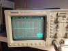
Of the two display chips, the Frequency read out side will not display properly in either of its two fields.
I am sure the numbers are correct, but just not readable.
Something seems to be wrong with Frequency display board (A1 display PCA), Amplitude display works fine.
If it were something in the latches or buffers, I would think that only a partial frailer of the frequency display would be seen.
As it is, the whole display is affected.
I am thinking of checking the filament voltages between the two displays?
I was wondering if anyone can help with the problem, or recommend a parts supplier.
Attached is a picture of the display, depicting the problem.
I would appreciate any help.
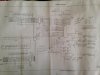
Added picture of the unit opened up.
I think if I can’t get a replacement board lined up, It would be nuts to dig into this.
The unit works fine – you punch in the numbers and you know what the display says any way.
At 4.7k to replace you have to judge how far you’re willing to go.
I am sure the numbers are correct, but just not readable.
Something seems to be wrong with Frequency display board (A1 display PCA), Amplitude display works fine.
If it were something in the latches or buffers, I would think that only a partial frailer of the frequency display would be seen.
As it is, the whole display is affected.
I am thinking of checking the filament voltages between the two displays?
I was wondering if anyone can help with the problem, or recommend a parts supplier.
Attached is a picture of the display, depicting the problem.
I would appreciate any help.
Added picture of the unit opened up.
I think if I can’t get a replacement board lined up, It would be nuts to dig into this.
The unit works fine – you punch in the numbers and you know what the display says any way.
At 4.7k to replace you have to judge how far you’re willing to go.
Attachments


Last edited: