Hi,
I am currently working on a project and I would like to see if I am on the right track.
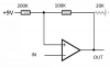
Using a 9V battery supply I have a hall effect sensor (2SS52M, Hall Effect Sensor, Omnipolar, 2.5mT, 3.8 → 30 V dc, 3-Pin TO-92) which will output to a Schmitt trigger (TC4S584F(F)).
I want to know, is my output voltage from the schmitt still +9V?
with these values is my high V point approx. 2.0V and low V point approx. .6V?
Basically I want the hall effect sensor to light an LED when magnetic flux leakage has been detected. Any help greatly appreciated!
I am currently working on a project and I would like to see if I am on the right track.
Using a 9V battery supply I have a hall effect sensor (2SS52M, Hall Effect Sensor, Omnipolar, 2.5mT, 3.8 → 30 V dc, 3-Pin TO-92) which will output to a Schmitt trigger (TC4S584F(F)).
I want to know, is my output voltage from the schmitt still +9V?
with these values is my high V point approx. 2.0V and low V point approx. .6V?
Basically I want the hall effect sensor to light an LED when magnetic flux leakage has been detected. Any help greatly appreciated!


