If you remove the transistor and it still works then you have a problem because without the transistor in the circuit there is no path from the input to the output so the output will remain as a fixed and unchanging 5V.
But there's way more wrong.
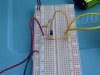
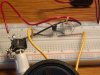
Now you show more of your circuit and what you're trying to do with it (and that's helpful)
Somehow you have decided to connect your input straight across your battery. That is nothing like what is shown on the schematic. Why have you connected the base resistor to your power supply? This should be connected to your input.
Also now I can see that you're using this to amplify audio. Whilst it's kinda going to work, there are major problems as this circuit is not designed to amplify audio. At low voltages like this the speaker won't actually be damaged, but the DC you're putting through it is not what it is designed for.
However, let's get it working (as I said, you're unlikely to damage anything).
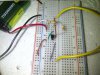
Connect R2 between the base and your input signal, and DO NOT connect it to anything else.
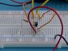
Do you know which way the conductors run on these prototyping boards? You may be confused by it.
This site explains it well. Your use of the power lines is fine (it differs from his recommendation)
edit: the break in the power bars is not always present. It pays to check. Making an assumption either way can spoil your day.


")