Homemade automatic plant waterer

tobocop

Jul 29, 2014
3
Joined
Jul 29, 2014
Messages
3
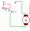
Does any one know how well this would work? The potentiometer is a substitute for a plant, the idea being that as the moisture in the pot decreased the resistance would increase, activating the motor which would pump water into the pot.
 

Attachments

  • Screen Shot 2014-07-29 at 3.44.45 PM.png
    Screen Shot 2014-07-29 at 3.44.45 PM.png
    19 KB · Views: 222

(*steve*)

¡sǝpodᴉʇuɐ ǝɥʇ ɹɐǝɥd
Moderator
Jan 21, 2010
25,510
Joined
Jan 21, 2010
Messages
25,510
My guess is that the motor would either always be off (best guess) or always on (unlikely).

If the SCR has a very sensitive gate, you *might* get enough current through the 100k resistor (shown as a pot, but not connected in a useful way) to turn it on.

In this circuit a decreased resistance would cause the SCR to trigger. And in any case, once it's on, it will stay on (presuming enough current flows through it).

You need a circuit that is turned off when the resistance drops. And you probably want the trigger point adjustable because some plants and some soils may require different amounts of water (or change resistance differently).

I can think of a fairly complex circuit using a comparator which might work (well, it's complex compared to this) but maybe someone else can post a simple circuit that might work.
 

shumifan50

Jan 16, 2014
579
Joined
Jan 16, 2014
Messages
579
Buy a Gardena watering computer for around£30 that just works. It comes with a moisture sensor, I use those to water my Rhododendrons that I value highly and they have never failed me.
 

tobocop

Jul 29, 2014
3
Joined
Jul 29, 2014
Messages
3
My guess is that the motor would either always be off (best guess) or always on (unlikely).

If the SCR has a very sensitive gate, you *might* get enough current through the 100k resistor (shown as a pot, but not connected in a useful way) to turn it on.

In this circuit a decreased resistance would cause the SCR to trigger. And in any case, once it's on, it will stay on (presuming enough current flows through it).

You need a circuit that is turned off when the resistance drops. And you probably want the trigger point adjustable because some plants and some soils may require different amounts of water (or change resistance differently).

I can think of a fairly complex circuit using a comparator which might work (well, it's complex compared to this) but maybe someone else can post a simple circuit that might work.
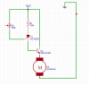
maybe I don't understand this at all, but would it work if you replaced the SCR and the NPN transistor with a PNP transistor, meaning that as the resistance of the flower pot increased there would be less positive voltage on the gate of the PNP, triggering it? or do i just have a bad understanding of voltage?
 

Attachments

  • Screen Shot 2014-07-29 at 10.36.08 PM.png
    Screen Shot 2014-07-29 at 10.36.08 PM.png
    14.9 KB · Views: 179

KrisBlueNZ

Sadly passed away in 2015
Nov 28, 2011
8,393
Joined
Nov 28, 2011
Messages
8,393
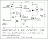
Here's what I suggest. It's a two-transistor Schmitt trigger (Q1,2) driving an N-channel MOSFET (Q3) that drives the watering pump (M1) directly. It requires a 12V supply.
269602.001.GIF

VR1 and the soil between the probes form a voltage divider that determines the voltage at the bottom end of R1. Damper soil pulls that voltage towards 0V. This biases Q1 ON, which turns Q2 OFF, so Q3's gate voltage is 0V and the watering pump doesn't run.

In this state, there is no current through VR2, so Q1's emitter sits close to +12V regardless of the setting of VR2.

As the soil dries out, the voltage on R1 increases, until a point is reached where there is not enough voltage across Q1's base-emitter junction to keep it conducting. As it begins to conduct less, and its collector voltage falls, Q2 starts to conduct. As soon as this happens, current through VR2 pulls Q1's emitter down below the +12V rail, turning Q1 OFF even more.

This action is called positive feedback and it results in a very quick and clean transition from one state to the other.

In the new state, Q1 is OFF (and it won't turn ON again until moisture in the soil pulls its base voltage quite a bit further towards 0V, because its emitter is now at a lower voltage than it used to be), and Q2 is ON.

Current through Q2 causes a voltage drop across VR2 (which provides the reduced emitter voltage for Q1), and R3, which provides the positive voltage (through R4) to Q3's gate to make Q3 conduct and energise the watering pump.

When the soil at the probes becomes wet enough, Q1's base voltage will drop far enough for the process to reverse, also with a snap-like action, turning the pump OFF.

D1 protects Q3 against the back EMF produced by the pump due to its inductive nature, when its supply current is interrupted by Q3 turning OFF.

R1 provides protection for Q1 and VR1 in case the soil probes are accidentally shorted to something, or shorted together.

The setting of VR1 determines the soil dryness threshold for the pump turning ON. The setting of VR2 determines the hysteresis of the Schmitt trigger circuit; that is, the distance between the dryness threshold for turning the pump ON, and the dryness threshold for turning the pump OFF. The further apart these thresholds are, the longer the pump will run on each activation.

The amount of water delivered on each activation will depend on several factors as well as the setting of VR2: the distance between the water entry and the probes, and the speed of the pump, and other factors. Use some trial and error.
 
Last edited:

Audioguru

Sep 24, 2016
3,656
Joined
Sep 24, 2016
Messages
3,656
I made a circuit that lights an LED when a plant becomes dry. But pure water does not conduct, fertilizer or salts in water causes some conduction and my tap water conducts a lot.

Your probes should use AC because DC causes plating and corrosion.
 

NMNeil

Oct 3, 2014
111
Joined
Oct 3, 2014
Messages
111
I can think of a fairly complex circuit using a comparator which might work (well, it's complex compared to this) but maybe someone else can post a simple circuit that might work.

Perhaps this?

 
Top