How to monitor an actuator's feedback line from a microcontroller?

markdire

Aug 31, 2018
4
Joined
Aug 31, 2018
Messages
4
ZdnVE.jpg


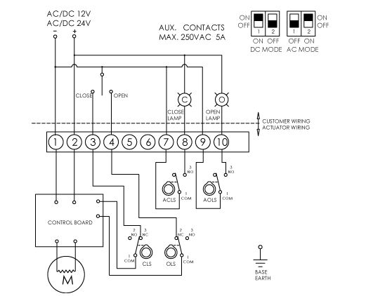
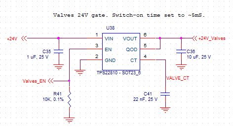
the AG-020-B electric actuator is controlled from a microcontroller. Terminal 1 is connected to the DC PSU GND, Terminal 2 is connected to the +24VDC via a high side Power MOSFET(TPS22810) as shown below. This is for power saving.
HLYUX.jpg


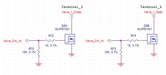
Low side MOSFET (AUIPS1021) Q5A and Q5B are used to control the opening/closing of the valve via terminal 3 and 4. The microcontroller I/O lines Valve_Ctrl_1a and Valve_Ctrl_1b provide a 3.3V signal.
aAMnr.jpg


- Comments are welcome regarding the power and switching circuitry.

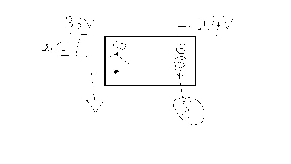
- Any suggestion on how to monitor the feedback lines on terminal 8 and 10 from a microcontroller. A lamp is not suitable as the system will be enclosed in a box. I've come up with a relay as a possible solution but I would rather use discrete devices.
MhkaA.jpg
 

WHONOES

May 20, 2017
1,242
Joined
May 20, 2017
Messages
1,242
How about a resistor to pin 8 with a 3.3V zener at the ground end with the junction of the two connected to your μP.
Then a 1 would represent "open" and a 0 "closed". Same on pin 10. This assumes that the supply is dc not ac.
 

markdire

Aug 31, 2018
4
Joined
Aug 31, 2018
Messages
4
How about a resistor to pin 8 with a 3.3V zener at the ground end with the junction of the two connected to your μP.
Then a 1 would represent "open" and a 0 "closed". Same on pin 10. This assumes that the supply is dc not ac.
Would you mind drawing a diagram?
 

Alec_t

Jul 7, 2015
3,817
Joined
Jul 7, 2015
Messages
3,817
How about
SwitchStatusMonitor.PNG
This assumes pins 7-10 are not connected to any other supply.
 

WHONOES

May 20, 2017
1,242
Joined
May 20, 2017
Messages
1,242
Got around to doing your sketch. See attachment.
Couldn't be simpler.
Circuit is same for both.
 

Attachments

  • resistor and zener0001.jpg
    resistor and zener0001.jpg
    30.6 KB · Views: 20

markdire

Aug 31, 2018
4
Joined
Aug 31, 2018
Messages
4
Got around to doing your sketch. See attachment.
Couldn't be simpler.
Circuit is same for both.
There is no actual lamp in the real thing, it's just an example from the datasheet. And you have only access to one side of terminal 8 (customer wiring)
 
Top