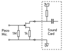
"L6" - what kind of transistor?

muragavino

Aug 10, 2015
5
Joined
Aug 10, 2015
Messages
5
Hi There!

Could anybody help me to find a specific transistor for a preamplifier for Piezo pickups? The preamp works with the 3.3V feed out of e.g. a PC mircophone input (Phantom).

In the attachment I prepared a schematic of the preamp. Please help me to understand what transitor is used here.

Thanks!

View attachment Unknown FET.pdf


audioguru2

Apr 6, 2004
12,026
Joined
Apr 6, 2004
Messages
12,026
You forgot to tell us what the pickup is used for. A guitar? A piano? A drum? The horrible circuit will work with an N-channel Jfet or NPN transistor if the piezo pickup is in a drum. 

The circuit will not be a linear amplifier with a high input impedance if a Jfet is used. The circuit is designed to use an NPN transistor but will work poorly when a piezo pickup or magnetic guitar is used because its input impedance is too low.

If an N-channel Jfet is used then its gate must have a 2.7M resistor to 0V, not to its output. Use a 2N5457 or 2N5484.


muragavino

Aug 10, 2015
5
Joined
Aug 10, 2015
Messages
5
Hi audioguru,

thanks for the fast reply!

The pickup is a simple piezo-disc (buzzer) used in a very cheap throat microphone. Since it wasn´t doing its job - sound was heard from all directions, not only from the throat - I have meliorated the throat-mic by acoustic means using silicon gel as sound conductor and expanded rubber as isolator. Now it works just lovely!

As a matter of fact, it works that well, that I wanted to make some more on my own account, but I can´t figure out which transistor to use. The "horrible circuit" works actually very well.

Searching the internet I now found as possible candidate the 2SC1623-L6, which has "L6" printed on the SOT23 housing, and which is a NPN. Do you think this transistor is possible?

Thanks again,

Michael


muragavino

Aug 10, 2015
5
Joined
Aug 10, 2015
Messages
5
I just copied it from the PCB that was in the throat-mic housing. It is a single layer PCB and simple enough not to make any error.


audioguru2

Apr 6, 2004
12,026
Joined
Apr 6, 2004
Messages
12,026

muragavino

Aug 10, 2015
5
Joined
Aug 10, 2015
Messages
5
Thank you very much, audioguru, for your advise and detailed information.

These two schematics posted by audioguru, work both with 9V. Could they work with 3.3V?

What I need is a circuit to work with the 3.3V you can get out of a PC-mic input, where the tip of the phone jack caries the audio signal, the ring is connected via a resistor of 2.2k to 3.3V, and the sleeve goes to GND. Since the preamps in the PCs do always have a decoupling cap, ring and tip can safely be shorted to supply the 3.3V as phantom power.

Thanks again!


audioguru2

Apr 6, 2004
12,026
Joined
Apr 6, 2004
Messages
12,026
The circuit you found works with any little NPN transistor including a 2SC1623, it is not a Jfet. It has a low input impedance which loads down the signal level from the high output impedance of a piezo mic and the transistor has low voltage gain so if you speak loudly you will make an output.


Hero999

Oct 28, 2007
2,433
Joined
Oct 28, 2007
Messages
2,433
The sound card needs to form part of the circuit.

Try this.

Jfet pre-amp.png


muragavino

Aug 10, 2015
5
Joined
Aug 10, 2015
Messages
5
Thanks Hero999, I will order some FETs like the above mentioned 2N5457 or 2N5484 and give it a try as soon as I have the parts. The results I will publish here.

Thank you all for your help, it is great to meet you guys!

 
Top