LED blinking with switch

vead

Nov 27, 2011
473
Joined
Nov 27, 2011
Messages
473
I am trying to blink led with switch
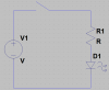
I have one switch and one LED.
switch is connected to port pin PO.0
LED is connected to port pin P1.0

if switch is on then LED is on
if switch is of then LED is of
assembly code
Code:
org   0h
ON:
        setb P1.0         ;    led on
        setb  P0.0           ; switch is on
     
OFF:
        clr P1.0           ; led off
        clr P0.0             ; switch is off
main:
       
          jb P0.0,  ON      ; switch is closed
        jnb P0.0, OFF       ; switch is open
     
        sjmp main

         end

whats the problem , Led is not blinking
 

Attachments

  • upload_2014-9-18_22-31-24.png
    upload_2014-9-18_22-31-24.png
    4.6 KB · Views: 156
Last edited:

Harald Kapp

Moderator
Moderator
Nov 17, 2011
14,271
Joined
Nov 17, 2011
Messages
14,271
What happens when the controller executes this line and the switch is on?:
Code:
jb P0.0,  ON      ; switch is closed
It will jump to the address labeled ON, turn on the LEd, continue to OFF, turn off the LED and come back to the adddress labeled main.
What happens when the controller executes this line and the switch is off?:
Code:
jnb P0.0, OFF       ; switch is open
It will jump to the adddress labeled OFF, turn off the LED and come back to the adddress labeled main.
For you the LED will always be off.

Your fault is in not providing a jump back to main from the routines at ON and OFF. One way to corect this is as follows (note that there are other ways which may be more efficient as the program grows larger:
Code:
org   0h

main:
     
        jb P0.0,  ON      ; switch is closed
        jnb P0.0, OFF    ; switch is open
   
        sjmp main

ON:
        setb P1.0         ;    led on
        sjmp main       ; return to main for checking the state of the switch
   
OFF:
        clr P1.0           ; led off
        sjmp main       ; return to main for checking the state of the switch

         end

Note that the line
Code:
setb  P0.0           ; switch is on
under the label ON as well as the line
Code:
clr P0.0             ; switch is off
under the label OFf in your code is nonsense. You read the state of the input pin, you do not set is. Setting the state is achieved by actuating the external switch connected to P0.0


Your image is too small. I cannot clearly see whther the connection of the switch is correct. It looks a bit supsect from what I can see. A bigger image would clearly help.
 

Harald Kapp

Moderator
Moderator
Nov 17, 2011
14,271
Joined
Nov 17, 2011
Messages
14,271
Just for the fun of it, here's an alternative solution :D

bla-png.15328


I know, that's not what you want, I just wanted to pull your leg...
 

Attachments

  • bla.png
    bla.png
    3.7 KB · Views: 278

(*steve*)

¡sǝpodᴉʇuɐ ǝɥʇ ɹɐǝɥd
Moderator
Jan 21, 2010
25,510
Joined
Jan 21, 2010
Messages
25,510
at the end of the section labelled with ON:, what happens next? How fast does this happen?

Are you reading from or writing to the P0.0 signal? Have you set up which are inputs and which are outputs? How do you make a delay so that you can see it flash?

You have lots of things to consider.

Also where does the program start? is this a good place? Should you get it to start elsewhere or do something else first?
 

KrisBlueNZ

Sadly passed away in 2015
Nov 28, 2011
8,393
Joined
Nov 28, 2011
Messages
8,393
The 8051 uses "quasi-bidirectional" I/O. If you want to use an I/O pin as an input, your firmware has to set it high and leave it high. The external circuit can then pull it low and you can read it on the port register. Your firmware should never use the instruction CLR P0.0. As soon as you do that, P0.0 will always read low regardless of the state of the switch.

Edit: This is not the only problem with your code. See Harald and Steve's responses.
 

vead

Nov 27, 2011
473
Joined
Nov 27, 2011
Messages
473
Is this a homework question?

No actually I am doing all by myself I want to learn something by doing some practical
I don't think so. Vead seems to be pursuing this on his own.
my target
First I have decided I will make simple project (for LED, SWITCH,MOTOR,SEVEN SEGMENT DISPLAY ) I will make diagram. then I will write assembly code , then I will write c code. first I will write code for 8051 and then I will write for Arm controller

Your image is too small. I cannot clearly see whther the connection of the switch is correct. It looks a bit supsect from what I can see. A bigger image would clearly help.
look here

I am using this code but still led is not blinking
Code:
org   0h

main:
    
        jb P0.0,        ; switch is closed
        jnb P0.0,     ; switch is open
  
        sjmp main

ON:
        setb P1.0         ;    led on
        sjmp main       ; return to main for checking the state of the switch
  
OFF:
        clr P1.0           ; led off
        sjmp main       ; return to main for checking the state of the switch

         end
 

Harald Kapp

Moderator
Moderator
Nov 17, 2011
14,271
Joined
Nov 17, 2011
Messages
14,271
Consider Kris' tip. Set P0.0 to high:
Code:
org   0h

main:
       setb  P0.0  ; switch is on

loop:
        jb P0.0        ; switch is closed
        jnb P0.0     ; activate P0.0 as input
 
        sjmp loop

ON:
        setb P1.0         ; led on
        sjmp loop         ; return to loop for checking the state of the switch
 
OFF:
        clr P1.0           ; led off
        sjmp loop        ; return to loop for checking the state of the switch

         end
 

KrisBlueNZ

Sadly passed away in 2015
Nov 28, 2011
8,393
Joined
Nov 28, 2011
Messages
8,393
Code:
        jb      P0.0,        ; switch is closed
        jnb     P0.0,     ; switch is open
Those lines are not valid instrutions. The JB and JNB instructions require a label for the MCU to jump to if the condition is true.

Your schematic in post #8 still has errors.
  • R1 cannot be 110k beause that will not provide enough current to light the LED. Use something like 470Ω instead.
  • R2 should be around 10k.
  • C3 should be around 100 nF.
This code should work:
Code:
 1         org     0
 2
 3 Main:
 4         setb    P0.0            ; Set P0.0 (pushbutton pin) high so it can be used as an input
 5 MLoop:  jnb     P0.0,PB_On      ; If pushbutton pin is low, pushbutton is closed, so go to PB_On.
 6         setb    P1.0            ; If MCU gets here, pushbutton is open. Turn the LED OFF.
 7         sjmp    MLoop           ; Test again, forever
 8 PB_On:  clr     P1.0            ; Pushbutton is ON. Turn the LED ON.
 9         sjmp     MLoop          ; Test again, forever
10
11         end

At line 4, the code sets P0.0 high. This puts this pin into "input" mode, where an external circuit (the pushbutton) can pull it low. A "weak pullup" resistor in the MCU pulls it high, but the pushbutton can easily force the input low. This allows you to read the pushbutton state by reading P0.0. Your code must leave P0.0 set high (even though it will read low if the pushbutton is closed).

At line 5, the code tests the state of the pushbutton input using a JNB instruction. This instruction has two operands: the bit reference for the port input to be tested, and a label that the MCU will jump to, if the condition is met. In this case, the condition is "NB", i.e. bit is zero. So when the MCU executes that instruction, it will test the state of the pushbutton input; if the pushbutton is pressed, it will read a 0 for the bit, and the MCU will branch to the label given, which is PB_On. If the pushbutton is not pressed, it will read a 1 for the bit, and will not branch. It will just continue, and execute the next instruction at line 6.

Line 6 will be reached if the pushbutton is not pressed. It turns the LED OFF. Then line 7 jumps back to the start of the loop.

Line 8 is the PB_On label. The MCU will execute this line if the JNB instruction at line 5 detected that the state of P0.0 (the pushbutton input) was 0, i.e. the pushbutton was pressed. This line turns the LED ON, then line 9 jumps back to the start of the loop.
 

vead

Nov 27, 2011
473
Joined
Nov 27, 2011
Messages
473
Consider Kris' tip. Set P0.0 to high:
Code:
org   0h

main:
       setb  P0.0  ; switch is on

loop:
        jb P0.0        ; switch is closed
        jnb P0.0     ; activate P0.0 as input

        sjmp loop

ON:
        setb P1.0         ; led on
        sjmp loop         ; return to loop for checking the state of the switch

OFF:
        clr P1.0           ; led off
        sjmp loop        ; return to loop for checking the state of the switch

         end
I have compiled this code
there is two error

I tried your code. there is no error but still LED is not blinking
I corrected my circuit and then I burned code


KrisBlueNZ

Sadly passed away in 2015
Nov 28, 2011
8,393
Joined
Nov 28, 2011
Messages
8,393
Your diagram is too small to read properly.

You have not made all of the changes I listed for your schematic.

We are trying to help but it is quite frustrating when we repeatedly point out mistakes and you do not fix them.

Make the changes to the schematic and post it in a readable form.
 

vead

Nov 27, 2011
473
Joined
Nov 27, 2011
Messages
473
Your diagram is too small to read properly.

You have not made all of the changes I listed for your schematic.

We are trying to help but it is quite frustrating when we repeatedly point out mistakes and you do not fix them.

Make the changes to the schematic and post it in a readable form.
now I have reduced value of r1
 

KrisBlueNZ

Sadly passed away in 2015
Nov 28, 2011
8,393
Joined
Nov 28, 2011
Messages
8,393
Your circuit looks OK.

What do you expect that code to do? The LED will not blink. It will just follow the state of the pushbutton.
 

Harald Kapp

Moderator
Moderator
Nov 17, 2011
14,271
Joined
Nov 17, 2011
Messages
14,271
The LED will not blink. It will just follow the state of the pushbutton.
I guess that's what vead means. Looking at his post #1:
if switch is on then LED is on
if switch is of then LED is of

@vead:
now I have reduced value of r1
What's that supposed to tell us? Does the circuit work as expected, or not? If not, What do you expect, what happens instead?
 
Top