Sir jimkelly . . . Ver1.01
IN MY MAGGING THAT IMAGE RIGHT ON UP . . . . . 600x . . . just at pixelation onsetting
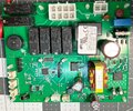
What this 'ole boys eyesareaseeeeeeeing . . . . . . is a the utilization of a temporary charge duration. . . . . .
SUPER E-capacitor . . . . . . being used, instead of a battery and a nearby 12.6 Mhz System clock oscillator (for u/p clock) and a nearby 8 pin EEPROM 24xx series (it needing NO memory power backup) program memory storage chip and a ST brand 32 pin system controller -u/processor up at near top.
It has one output port set feeding into the
ULN2003 relay driver at the extreme top for the units multiple relays . . . . count 'em ! . . . . function switchings.
The board is being
IPON conformal coated and has
MULTIPLE surfactal leveling aberrations . . . . . particularly near and around multi connection components . . . . .thus leading to the shotgun multi directional light reflections .
That is making some think that the soldermanship or any detritus presence is being ch!tty ch!tty bang bang.
You show
ONLY this controller board *** . . .
*** BTW these people made it for
( Captain) MARVEL ICE MAKER . . . . escapades
***

www.lae-electronic.com
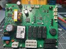
But there is the COMPANION board inside the unit with its temp display and assuredly an up and down temp push button set. PLUS the units temp sensor . . . . . which might have gone bad . . . or you have connections and inter wiring, yet to confirm as being good.
With there being no plug in connector in-continuity or a timely corrosive / oxidation build up onset.
We have yet to see a photo of that other board . . . but there is a 4 pin connector between the two boards, of which you can see the connector marked as
COMM on your board.
Starting at the right end pin we see it connected to DC power. The next pin is ground.
We know that those two connections are a complete loop, since your display is working.
The next two pins are are being In/Out serial digital handshaking lines that transport data between the two boards. Both are having .1 uf monolithic ceramic block cap bypassing at the pins and further on down there is a set of series 100 ohm surface mount resistors in line before further connecting to 2 ports on the ST u/P.
Do as the display is telling you . . . . . confirm any loss of connectivity between / or / on the boards and find the temp sensor and confirm its changing resistance with temp change . . . . . or having the presence of a good junction in case . . . . instead . . . . if they are using a 1N4148 family of diode as a temp sensor.
Vell now . . . . after I'm dun bin tellink you . . . . . vat isht you dun bin thinkink ?
(a la Herr Kapp)
I now be . . . . . . .
. . . . . . .
ZUJ'
ing
73's de Edd . . . . .
I just released my own fragrance . . . . . . but no one in the car seemed to like it.
.