The problem you have is that the capacitor gets a voltage on it that is roughly related to the PWM mark/space ratio, but what happens from there can get very screwy very quickly.
Before the voltage on the capacitor gets to 0.7V, nothing happens -- there is a "dead" zone.
Now, let's look at the load. I'll assume it is a LED with a Vf of 1.7V and a series resistor of around 825 ohms (to get a current of 4 mA at 5V as per the specs)
At 2V, the current will be about 0.4mA, and at 10V it will be around 10mA.
So, as voltage across the capacitor rises, the base current increases. The transistor amplifies this current, and at some point it gets to about 0.4mA -- the current required to have 2V across the load. If we assume a current gain of 200, the voltage across the capacitor at this point is 0.7 + (0.0004*10000)/200 = 0.02V -- so the threshold for action is 14.5% duty cycle.
As the duty cycle increases further, the current available to the base increases, until the collector current reaches 10mA. This will be at 0.7 + (0.01*10000)/200 = 1.2V which is 24% duty cycle.
So all your control is in a small range of duty cycles, say around 10%. This range will vary in size depending on the transistor and temperature, the actual current drawn by the load, and certain other factors (the non-linearity as the transistor approaches saturation has not been considered earlier).
A better approach is to either employ a level converter to alter the output of the PIC from 0-5V to 0-10V and then integrate this, or to employ an amplifier with a gain of 2 to transfer the voltage across the capacitor to the load. (A more fancy approach is to have a gain of 1.6 and an offset voltage on the output of 2V)
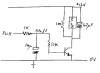
In the former case, you could employ a circuit like this to change the level:
(That was prepared for another use, so please ignore the 12V rail)
This will produce a near 12V swing from the PIC output, and will drive significant current. It is shown here driving a mosfet, but imagine that is a capacitor.
The resistor in series with the capacitor needs to allow a current that is large enough so that the current drawn by the load (it will be placed across the capacitor) does not load the circuit too much. I would suggest a value of around 68 ohms. This will limit the max voltage across the load to under 10V, so maybe you need a higher supply rail... Then you need a capacitor large enough that the ripple will be low.
Large currents mean it's not the best solution.
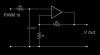
The op-amp solution is better:
For this you require an op amp with an input common mode range which includes the negative supply rail, and which can swing the outputs to the supply rails (or very close to the +ve one)
If you want to bias the output so you get a 2V to 10V output for a 0 to 100% mark/space ratio (essentially 0V to 5V input), look
here.