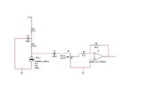
noise cancelling circuit

1

1time

Jan 1, 1970
0
just came accross an analog circuit that can be used to implement noise cancelling headphones and decided to try it out. im using the lm324n opamp. audio in signal is being received at the output but with a lot of hissing sound but no noise reduction. measured the output of the mic input opap but there is little to no amplification. any hints?? plus any suggestions on other circuit parts are most welcome
circuit.JPG


audioguru2

Apr 6, 2004
12,026
Joined
Apr 6, 2004
Messages
12,026
The lousy old LM324 is horrible for audio. It is noisy (hiss), has crossover distortion and has trouble above only 2kHz.

C4 in your circuit reduces frequencies above only 500Hz.
You show an opamp driving headphones which might be impossible because an opamp has a low output current.

Which type of mic do you have? Your circuit has a low input impedance and does not power an electret mic.

For noise reduction the mic must be very close to an earphone and have a switch to change the polarity so there is negative feedback. Positive feedback will cause feedback howling.

 
1

1time

Jan 1, 1970
0
have an electret microphone and have a separate circuit for controlling the input. will upload soon. according to the circuits brief description the noise cancellation is limited to the 500hz for purposes of stability
i had connected the headphones directly. a friend told me to have a look at an audio amplifier for the headphones but havent worked with one. any good alternative to the lm324n?
mic is placed right in the headphone earcup. wont the 3 stage opamp eventually invert the noise signal?


audioguru2

Apr 6, 2004
12,026
Joined
Apr 6, 2004
Messages
12,026
You do not place the mic inside the earphone cup because then it will try to cancel the wanted signal. It is mounted on the outside of the earphone cup so it hears the noise but does not hear the signal.

You do not reduce the high frequencies from the signal, you cut high frequencies from the mic sound if there are instabilities.

You need a balance control to adjust the gain of the mic amplifier.

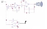
Your circuit is missing all the important details. The opamps and electret mic are not powered and a coupling capacitor is missing. The opamps are not biased.

If you looked in Google for a Noise Cancelling Circuit then you would have found this one:
http://gilmore2.chem.northwestern.edu/projects/noise_prj.htm
It does not cut all the high frequencies out of the signal, has a phase switch and has a mic level control.

It uses old NE5532 audio opamps that can drive 600 ohms headphones.

 
1

1time

Jan 1, 1970
0
tried out the TL-084 quad opamps and they are far much better, the audio is clearer though main drawback is requiring negative and positive supply but its a small price to pay. i guess the microphone input requires a pre-amplifier and an amplifier i.e. two stage amplification, preferably using an audio amplifier such as the LM-386 audioamp IC.
attached is the microphone circuitry in had promised to upload.

mic.JPG


audioguru2

Apr 6, 2004
12,026
Joined
Apr 6, 2004
Messages
12,026
tried out the TL-084 quad opamps and they are far much better, the audio is clearer though main drawback is requiring negative and positive supply
If the opamp is simply biased at half the supply voltage with two resistors and a filter capacitor then a single supply can be used.

i guess the microphone input requires a pre-amplifier
You do show a preamp opamp (but with gain much too small) but it is inverting with a very low input resistance (1k produced by R4) so the mic signal is loaded down and killed when the volume control is at max. A non-inverting opamp circuit should be used because it has a high input resistance.
You should use a TL074 because it is a TL084 that is selected for low noise (low hiss).

Your 220uF coupling capacitor C2 is much too large.

... and an amplifier i.e. two stage amplification, preferably using an audio amplifier such as the LM-386 audioamp IC.
The output amp must be able to drive your load impedance. I don't think anybody still uses 8 ohms headphones. Some opamps can drive 600 ohms headphones.
 

Kevin Weddle

Feb 23, 2004
1,620
Joined
Feb 23, 2004
Messages
1,620
The idea behind the noise cancelling headphones would appear to be only effective under certain conditions. Is a mic placed outside the earphone the way they are sold in stores?


audioguru2

Apr 6, 2004
12,026
Joined
Apr 6, 2004
Messages
12,026
KevinIV said:
The idea behind the noise cancelling headphones would appear to be only effective under certain conditions. Is a mic placed outside the earphone the way they are sold in stores?
In the link I posted, the mic is shown outside the headphones.View attachment 41235


Kevin Weddle

Feb 23, 2004
1,620
Joined
Feb 23, 2004
Messages
1,620
The theory behind it is to reduce what is in the original transmission. If it's not there, aren't you amplifying external noise?


audioguru2

Apr 6, 2004
12,026
Joined
Apr 6, 2004
Messages
12,026
The headphones "leak" noise from the outside. The mic picks up the noise (not the signal), the circuit inverts it then adds it to the headphones input so it cancels the noise.


Kevin Weddle

Feb 23, 2004
1,620
Joined
Feb 23, 2004
Messages
1,620
There is a polarity switch S1. It may also need a variable resistor circuit so the user can have an adjustment depending on the type and intensity of outside noise.


audioguru2

Apr 6, 2004
12,026
Joined
Apr 6, 2004
Messages
12,026
The project I posted has a volume control for the mic so it can be adjusted for almost perfect cancellation of the noise that leaks through the headphones.

 
Top