noob transistor question

kerpap

Jan 20, 2014
10
Joined
Jan 20, 2014
Messages
10
Hello,
em.. so I have a question about finding the right transistor.
I have a 3volt coin battery that operates a 3v relay switch.
I need an NPN transistor with a minimum base of 500ma and the collector and emitter to support 3V.

can someone suggest a transistor for me? I have a hard time with them.
:confused::eek:
 

(*steve*)

¡sǝpodᴉʇuɐ ǝɥʇ ɹɐǝɥd
Moderator
Jan 21, 2010
25,510
Joined
Jan 21, 2010
Messages
25,510
Firstly, some of what you say makes little sense.

with a minimum base of 500ma

However the rest makes some sort of sense.

I have a 3volt coin battery that operates a 3v relay switch.
Do you mean a relay? If so, you'll need to determine the current it requires and whether the coin battery can supply that current (and perhaps for how long)

I need an NPN transistor [...] and the collector and emitter to support 3V.
That's pretty easy. a 2N2222 or a BC548 are likely fine. They are rated for well above 3 volts, so no problems there.

Be aware that there will be some voltage drop across the transistor and this may prevent the relay from operating in the worst case.

You will also need to consider how you will drive the base in order to switch the transistor on fully without wasting power or damaging the transistor (in the worst case)

Can you provide some information on the relay and how you are planning to turn the transistor on?
 

kerpap

Jan 20, 2014
10
Joined
Jan 20, 2014
Messages
10
hi
sorry, I know it doesn't make seance, I am not very familiar with transistors.

what I have is a solar cell (5V 1400ma) and a battery pack (12v 1.6A) and a 3V coin battery.

the solar cell provides power to a raspberry pi. the relay will be used to kick over to the battery pack when the solar cell no longer provides enough power (cloud cover/nightfall)

so, I guessed that a 3V relay coil can be activated by a 3V coin battery. where the transistor comes in, is that a small amount of current from the solar cell would go to the base of the transistor and allow the coin battery to flow to the relay. the solar cell is connected to the N/O
once there is not enough current to supply power to the pi, there would also not be enough for the transistor thus cutting power from the coin battery and closing the relay (battery pack on N/C)

I can only spare about 500ma of power from the solar cell to the transistor.

I think I might have the wrong idea of how a transistor works

which, is why I am here :)
 

(*steve*)

¡sǝpodᴉʇuɐ ǝɥʇ ɹɐǝɥd
Moderator
Jan 21, 2010
25,510
Joined
Jan 21, 2010
Messages
25,510
Does your 12V battery pack get regulated to 5V before it powers the Raspberry Pi (Or can they be powered by 12V)?

There may be a far simpler solution.
 

kerpap

Jan 20, 2014
10
Joined
Jan 20, 2014
Messages
10
it can run on a range of 5V to 12V

I have run it off of USB power (5v 0.8A) and the battery pack that came with it was 12 volts.

I appreciate the help. I haven't messed around with electronics since I was a kid.
sorry if my questions are dumb.

I learn by doing.
 

kerpap

Jan 20, 2014
10
Joined
Jan 20, 2014
Messages
10
this is kinda what I had in mind.
schema.jpg
 

(*steve*)

¡sǝpodᴉʇuɐ ǝɥʇ ɹɐǝɥd
Moderator
Jan 21, 2010
25,510
Joined
Jan 21, 2010
Messages
25,510
According to this (and my Raspberry PI enabled colleague) the max voltage for the device is about 5.5V

I would recommend that you have a voltage regulator for both your solar panel and your battery pack.

The best option would be to have your solar panel regulated to 5.5V and your battery pack regulated to 5V, then use a pair of schottky diodes to allow the highest voltage power supply to power the raspberry pi. The battery would automatically take over as the solar panel was no longer able to power the device.

For efficiency you would choose a switchmode regulator. This would tend to get the most power from your solar panel as well as your battery.

However, I wonder what you're doing now. If you haven't blown up the raspberry pi then you must have some form of regulation. What are you using?

(Oh, and don't worry too much about switchmode regulators and schottky diodes. I'll show you where to get them and how to wire them up if that seems to be the best option)
 

kerpap

Jan 20, 2014
10
Joined
Jan 20, 2014
Messages
10
This thing may not be a Raspberry pi then. it is a small mini computer with wifi. I was sort of under the impression it was made from a raspberry pi.
anyways it came with a 12V AC adapter and a 12V battery pack however they sell an option to run off of USB. I have run the device using 5 and 12 volt supplies.

I have a 5V 1.4A solar cell that I can run it on fine.
 

(*steve*)

¡sǝpodᴉʇuɐ ǝɥʇ ɹɐǝɥd
Moderator
Jan 21, 2010
25,510
Joined
Jan 21, 2010
Messages
25,510
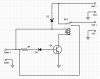
Here is a circuit that might do the trick for you. I'm not overly enthused by it, but it doesn't use a lot more than you originally required.

attachment.php


D1 is a zener diode, perhaps a 4V device? Q1 is a BC547 or similar (depending on the relay) The diode shown across the relay is required. It would be a 1N4001. Diode D2 is a 1A schottky diode. The value of R1 is probably around 100 ohms

Q1 starts to switch on switch on when the solar panel produces around 4.6V. When it turns on hard enough (probably around 5V), it will pull in the relay, powering the circuit from the solar panel.

When the voltage from the solar panel falls, the relay will drop out, powering the device from the battery.

Diode D2 prevents a loss of power from the device during switching. During this time, the device is powered from the solar panel.

There are some serious drawbacks. Firstly, the load from the device is likely to cause the voltage from the solar panel to fall dramatically. This will cause the relay to drop out. Then the voltage will rise and the relay will pull in, this will repeat until the solar panel can provide enough power to drive the load. It may cause the device some headaches, and may even remove power from the device for long enough to cause it to reset.

On the basis of the above, I don't think this is practical.

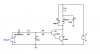
There are better solutions, but they're more complex.

Perhaps someone can come up with something that is both simple and reliable...
 

Attachments

  • SolarRelay.png
    SolarRelay.png
    17.2 KB · Views: 221

Arouse1973

Adam
Dec 18, 2013
5,178
Joined
Dec 18, 2013
Messages
5,178
I don't know if this might also work as a driver for the relay. I have added a soft start to allow the support cap to give some help to the relay. Then reduce the current to above it's holding current. just a thought
Adam
 

Attachments

  • RELAY.PNG
    RELAY.PNG
    5 KB · Views: 79

(*steve*)

¡sǝpodᴉʇuɐ ǝɥʇ ɹɐǝɥd
Moderator
Jan 21, 2010
25,510
Joined
Jan 21, 2010
Messages
25,510
Yeah, I also thought along those lines, but because the 12V comes from the battery, a static load (the relay) is probably not a great idea.

A better idea would be a pair of buck regulators, the battery connected to one set for 4.5V, the solar panels connected to one set for 5.5V. The output of these could be combined with a pair of schottky diodes.

The battery would just smoothly take over as the power from the solar panel dropped off.
 

Arouse1973

Adam
Dec 18, 2013
5,178
Joined
Dec 18, 2013
Messages
5,178
Yeah agreed. Thought I would keep it simple as you had.
Cheers
Adam
 
Top