Hi guys,
I'm interested in both repairing this thing and learning a little more about it. I'm an engineering major and have learned the physics behind electricity and magnetism, but I haven't yet taken circuits. All my knowledge is limited to projects I've done so far (populating PCBs, wiring car stereos, research on building an electric car, etc).
0) What is the device?
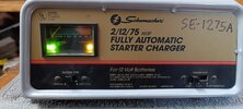
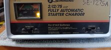
I've got an old (70s? 80s?) Schumacher SE-1275A battery charger that I want to fix.

It looks like the charger is still sold today. The graphics have changed, but the switches and meter are in the same locations and look exactly the same.
http://www.amazon.com/Schumacher-SE-1275A-Automatic-Onboard-Battery/dp/B000BO8TTY#productDetails
At the minimum, I'd like to use it to power an electrolysis bath. In other words, I don't mind losing the switch functionality as long as I can get power out of this thing.
1) What is the fault?
The problem is that it doesn't appear to work at 2A or 12A. When the charger is plugged in, the meter always points all the way to the left (not necessarily pegged, but within the "CHARGE" label).
I thought that maybe only the gauge was broken, but I've tried to charge dead batteries overnight and had no luck.
At 75A, it buzzes (as it always has) and it definitely puts out electricity as it makes my electrolysis bath bubble like crazy.
I measured voltage at the clamps at different switch positions and no load (no battery connected). Here's what I got:
Switch position: Voltage measured (+/- 1V)
2A: 8V
12A: 10V
75A: 12V
(Note that I did NOT measure amperage. Those are labels on the switch)
2) History of the fault
~10 years ago, when I first had this problem, I discovered that flicking the amperage switch back and forth would sometimes get me a reading on the meter. I tried to avoid flicking to 75A. After doing this a few times, flicking the switch stopped helping, and now it's always stuck at 100% with the "Full Charge" LED on.
3) Actions unspecified in the manual
I may have left this on 75A for too long, but nothing crazy (less than a minute). Flicking the switch probably wasn't good for the charger either.
It's never been reversed or shorted or anything like that.
4) Does anything look or smell burnt?
5) Do any components look "wrong"
See photos. Only the SCR(?) looks suspect, but I might just be seeing burned flux.
6) PHOTOS
These burned looking contacts belong to the SCR/thyristor. Only the two outer terminals are hooked up. The middle one is cut off and is not connected to anything.

I tested the thyristor using the procedure here (without desoldering it), and it seemed okay.
http://www.androiderode.com/how-to-check-a-scr-with-digital-multimeter/


Here's a couple shots of the circuit board:


Back of the Charge Rate switch:

Back of the meter (top) and battery chemistry switch (bottom). What does the meter do, anyway? Is it an ammeter that drops to 0 as voltage approaches 12v?:

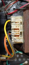
Switch/meter connections (In this picture, you are looking at the front of the charger, but I have lifted/rotated the front panel up and back like a garage door):

Don't know what this is. It's attached to the floor of the charger.


It sounds like these are diodes? There are two of these bolted to the same plate (heatsink?) as the SCR. I don't understand how these work - it looks like both terminals on the diode connect to the same place on the charger. Does the electricity flow from one side, through the heatsink,and into the other (e.g. white -> heatsink -> blue)?


FYI, I have some basic electronics knowledge - I've fixed a couple TVs, assembled a few PCBs, etc, but I'm still taking my first circuits course at school (I'm a software engineering major).
For kicks, here's a shot of my electrolysis tank. Looking forward to getting this up and running!

I'm interested in both repairing this thing and learning a little more about it. I'm an engineering major and have learned the physics behind electricity and magnetism, but I haven't yet taken circuits. All my knowledge is limited to projects I've done so far (populating PCBs, wiring car stereos, research on building an electric car, etc).
0) What is the device?
I've got an old (70s? 80s?) Schumacher SE-1275A battery charger that I want to fix.
It looks like the charger is still sold today. The graphics have changed, but the switches and meter are in the same locations and look exactly the same.
http://www.amazon.com/Schumacher-SE-1275A-Automatic-Onboard-Battery/dp/B000BO8TTY#productDetails
At the minimum, I'd like to use it to power an electrolysis bath. In other words, I don't mind losing the switch functionality as long as I can get power out of this thing.
1) What is the fault?
The problem is that it doesn't appear to work at 2A or 12A. When the charger is plugged in, the meter always points all the way to the left (not necessarily pegged, but within the "CHARGE" label).
I thought that maybe only the gauge was broken, but I've tried to charge dead batteries overnight and had no luck.
At 75A, it buzzes (as it always has) and it definitely puts out electricity as it makes my electrolysis bath bubble like crazy.
I measured voltage at the clamps at different switch positions and no load (no battery connected). Here's what I got:
Switch position: Voltage measured (+/- 1V)
2A: 8V
12A: 10V
75A: 12V
(Note that I did NOT measure amperage. Those are labels on the switch)
2) History of the fault
~10 years ago, when I first had this problem, I discovered that flicking the amperage switch back and forth would sometimes get me a reading on the meter. I tried to avoid flicking to 75A. After doing this a few times, flicking the switch stopped helping, and now it's always stuck at 100% with the "Full Charge" LED on.
3) Actions unspecified in the manual
I may have left this on 75A for too long, but nothing crazy (less than a minute). Flicking the switch probably wasn't good for the charger either.
It's never been reversed or shorted or anything like that.
4) Does anything look or smell burnt?
5) Do any components look "wrong"
See photos. Only the SCR(?) looks suspect, but I might just be seeing burned flux.
6) PHOTOS
These burned looking contacts belong to the SCR/thyristor. Only the two outer terminals are hooked up. The middle one is cut off and is not connected to anything.
I tested the thyristor using the procedure here (without desoldering it), and it seemed okay.
http://www.androiderode.com/how-to-check-a-scr-with-digital-multimeter/
Here's a couple shots of the circuit board:
Back of the Charge Rate switch:
Back of the meter (top) and battery chemistry switch (bottom). What does the meter do, anyway? Is it an ammeter that drops to 0 as voltage approaches 12v?:
Switch/meter connections (In this picture, you are looking at the front of the charger, but I have lifted/rotated the front panel up and back like a garage door):
Don't know what this is. It's attached to the floor of the charger.
It sounds like these are diodes? There are two of these bolted to the same plate (heatsink?) as the SCR. I don't understand how these work - it looks like both terminals on the diode connect to the same place on the charger. Does the electricity flow from one side, through the heatsink,and into the other (e.g. white -> heatsink -> blue)?
FYI, I have some basic electronics knowledge - I've fixed a couple TVs, assembled a few PCBs, etc, but I'm still taking my first circuits course at school (I'm a software engineering major).
For kicks, here's a shot of my electrolysis tank. Looking forward to getting this up and running!