epsolutions
- Sep 7, 2019
- 116
- Joined
- Sep 7, 2019
- Messages
- 116
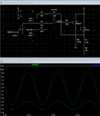
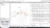
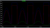
I created an amplifier in LTSpice as shown in the diagram and asc. file below. It is intended to accept a line level audio signal from a USB audio interface, and increase the voltage and current to drive a coil. The simulation indicates an output swing of about 0-9Vpp (blue trace). This is consistent with the parts and circuit topology. However, when constructed (twice from new parts), the circuit's gain only achieves half of that. IOW the output swings from 0V to only 4.5V, at which point it begins to clip if the gain is increased. I am aware that the offset and gain adjustments are interact, but I have tried all possible settings.
I am not sure what is happening. Judging by the sim plot, LTSpice wants to double whatever voltage I enter into V3. Maybe I am not using the correct analysis term? In the plot the 2.3V bipolar signal from the interface (green trace) is shown as reduced to 1.15V (purple) at pin 3 of the LM358.
1. Can anyone please help me understand why the built circuit's output voltage is low?
2. Why is this lack of gain not reflected in the simulation?
I posted on another forum but did not receive a detailed answer. I have tried to make my question here as clear as I can, in the hope someone can point me to the mistake.