PCB Component Removal

Ahr

Oct 3, 2025
2
Joined
Oct 3, 2025
Messages
2
I'm an 84 yo retiree who has only ever dabbled in electronics. I spent a 45 year career in IT, at all levels.

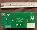
I have a small PCB from an indoor hydroponics device that I'm trying to repair for my wife. Research suggested that the likely problem was bad electrolytics. I bought replacements planning to remove the old ones that are thought to be faulty and to put new ones in.

I have a fair dabbler's workbench with a decent soldering iron and controller, solder removal mesh, solder sucker, etc. I've done a little of this on other projects. Note the 'little bit'.

On this project, I ran into a problem with the first capacitor. I was able to get the underside board pretty clear of solder, but I cannot get the connectors to release no matter how much heat I sink into the board.

As I said, I have very little experience. Are there tips, tricks and techniques for getting the connecting wires to give up their grip?
 

Attachments

  • solder removed.jpg
    solder removed.jpg
    156.3 KB · Views: 24
  • IMG_6439[1].JPG
    IMG_6439[1].JPG
    387 KB · Views: 24

Delta Prime

Jul 29, 2020
2,987
Joined
Jul 29, 2020
Messages
2,987
These could be snap in aluminum electrolytic capacitors. these capacitors must be properly discharged to prevent damage to other components on the board.
By the way D3 looks smoked. D3 is the component designator for the Diode occupying that footprint written in white on the silk screen.
For the capacitor, I would apply liberal amounts of flux rosin core solder and wiggle it out and or get wire cutters and crack them open and pull out each electrode, these two techniques will not damaging the board…easy Peezy lemon squeezy.
 
  • Like
Reactions: Ahr

Delta Prime

Jul 29, 2020
2,987
Joined
Jul 29, 2020
Messages
2,987
You must be patient that is a very large copper pour used for a ground plane so the surrounding area is expected to get hot that is normal.
 
  • Like
Reactions: Ahr

Externet

Aug 24, 2009
943
Joined
Aug 24, 2009
Messages
943
The capacitor body is helpful for holding it in a rocking motion while applying a well tinned high-power soldering iron for removing one pin at a time. As extra resource, behead the bad capacitor with cutters and drill its pins out for mounting a new one.
 
  • Like
Reactions: Ahr

ivak245

Jun 11, 2021
143
Joined
Jun 11, 2021
Messages
143
If it's a stubborn one, wedge a small flat blade screwdriver under the cap, and a little twist while the solder is molten will pop one leg out of the hole. Don't go overboard with the heat, as you may separate the pad from the board.
 
  • Like
Reactions: Ahr

ash_chook

Sep 13, 2021
1
Joined
Sep 13, 2021
Messages
1
With a little flux and the right sized clean and shiny iron tip you should be able to remove the cap, I would recommend a chisel tip not a round, you need the flat surface area of the tip to transfer the right amount of heat to go through the board, as recommended you may need a gentle rocking motion heating only one leg at a time, alternating until its out, then clean the holes for the replacement. Always apply flux and a small amount of fresh solder to assist in the wetting action and flow. Though hole plated boards with tight pins can sometimes be a challenges but simple double-sided boards should be straight forward. Enjoy your new hobby. regards ash
 
  • Like
Reactions: Ahr

davenn

Moderator
Sep 5, 2009
14,470
Joined
Sep 5, 2009
Messages
14,470
Research suggested that the likely problem was bad electrolytics.

the green coloured electro capacitor on the right side is definitely faulty, the top is well bulging
 
  • Like
Reactions: Ahr

Ahr

Oct 3, 2025
2
Joined
Oct 3, 2025
Messages
2
Thanks for all the replies and suggestions.
I'll try to remember to report efforts and results when I get back to this project.
 
Top