Plotter Cutter Help

trev

Apr 17, 2017
14
Joined
Apr 17, 2017
Messages
14
Hi I'm a newbie here.
I have a redsail 1360c plotter cutter or sticker cutter that is playing up- but don't know much about electronics.
when I turn it on with the switch the lcd screen flashes on, the plotter knife goes down and then it stops (screen off, knife up) and it does it again every second flash/ up/ down. it's supposed to travel to the right and be ready to cut with the lcd on. I bought it like this and the seller said it worked once from new and then did this , although it looks like it's done more work than one!
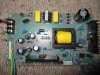
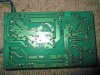
I looked inside and noticed the power supply circuit has 240v going in (which it does and the fuse is all good) and 3 connectors coming out - one fg - one 28v and lastly -8v -- the -8v reads about -5 and the 28v has nothing 0v coming out.
the board looks clean and nothing looks or smells burnt out - the 240v input goes up to a mosfet svf4n60f (far right) which seems to switch and then into a transformer (in the middle) that nothing seems to come out of-- a quick test of the diodes seems OK except maybe the mbrf 10200ct (middle bottom) which looks like doesn't stop the current as it should on the ohmeter (assuming it acts like 2 diodes joining at the middle pin. this mbr looks to end up on the 28v side.. does anyone know where should I check next, as I'm out of my depth!?
cheers trev
 

Attachments

  • circuit.jpg
    circuit.jpg
    306.9 KB · Views: 81
  • circuit2.jpg
    circuit2.jpg
    297.7 KB · Views: 86

(*steve*)

¡sǝpodᴉʇuɐ ǝɥʇ ɹɐǝɥd
Moderator
Jan 21, 2010
25,510
Joined
Jan 21, 2010
Messages
25,510
I would remove the double diode and check it out of circuit.
 

shrtrnd

Jan 15, 2010
3,901
Joined
Jan 15, 2010
Messages
3,901
Do you have a manual for this, or can you check on-line for one?
It sounds like a circuit problem, but with all the new stuff out there, I try to check the factory troubleshooting hints first, as a lot of devices come with safety interrupts.
Please be careful with the blade.
Is there a factory default setting or procedure to get there?
Is there a scrap paper piece or something blocking the blade or blade sensor?
Is there a 'start' position for the blade placement that is not where it's supposed to be?
Is the blade itself seated correctly, not misaligned or bent?
Is the blade depth correct, (blade fully seated)?
Is the belt, or whatever drives the blade holder aligned, (and not broken)?
Does the unit need to sense paper under the blade before it will engage the cutting function?
See if you can get a troubleshooting guide from the manufacturer or on-line.
 

trev

Apr 17, 2017
14
Joined
Apr 17, 2017
Messages
14
OK I took the double diode thing out and it checks out good unfort
and the chinese instructions are pretty scant- but none of the buttons seem to work and these's no mention of my problem..
I've tied every which way for the cutter mouse to work - but no luck..
any ideas of where to next?
cheers trev
 

trev

Apr 17, 2017
14
Joined
Apr 17, 2017
Messages
14
I mean't to say, I'm still looking at this power board as it's not producing 28v or -8v .. thanks for any electronic help..
 

(*steve*)

¡sǝpodᴉʇuɐ ǝɥʇ ɹɐǝɥd
Moderator
Jan 21, 2010
25,510
Joined
Jan 21, 2010
Messages
25,510
When powered on, is the power supply silent, or is it making a ticking sound?

Measure the resistance across the large diode (both ways) just above and left of the centre of the board. It's the black cylinder with the silver stripe near one end.
 

trev

Apr 17, 2017
14
Joined
Apr 17, 2017
Messages
14
hi steve no ticking and 470ohm with the red to the silver band and 360 the other way
 

trev

Apr 17, 2017
14
Joined
Apr 17, 2017
Messages
14
yes it's got 0 and 415 now - I suppose that's OK? it's got 403g written on it-
what about the 0v coming out of the transformer in the middle? it looks like 325vdc going in and between 100 and 300vdc on the middle pin from the mosfet..
 

(*steve*)

¡sǝpodᴉʇuɐ ǝɥʇ ɹɐǝɥd
Moderator
Jan 21, 2010
25,510
Joined
Jan 21, 2010
Messages
25,510
Yeah, 300VDC on the mosfet and AC to the transformer is correct.
 

trev

Apr 17, 2017
14
Joined
Apr 17, 2017
Messages
14
great- that's narrowing it down.. what about the 0v coming out of the transformer? it has 6 pins coming out that seem to be joined with an ohm check but nothing volt wise coming out when powered up--?
thanks for your input by the way steve- i'd be stuck without it
cheers
 

(*steve*)

¡sǝpodᴉʇuɐ ǝɥʇ ɹɐǝɥd
Moderator
Jan 21, 2010
25,510
Joined
Jan 21, 2010
Messages
25,510
What's coming out is very high frequency AC. If you're getting any output, the must be something coming out of the transformer.

And be reeeeeeealy careful measuring stuff with the power on. It's no exaggeration to say it can kill you.

Try putting a resistor (say 1k) across the output that's not zero. Does the voltage change?
 

trev

Apr 17, 2017
14
Joined
Apr 17, 2017
Messages
14
actually the board output has changed and now I'm, getting 3v where 28v should be and -.5v where -8v should be..(I think that changed when I put the mbr double diode back in) -and with a resister load test are you thinking that the 28v and -8v will only be there if connected to the main board on the machine- as I could plug it back in and check it, if I'm barking up the wrong tree totally! .. cheers
 

(*steve*)

¡sǝpodᴉʇuɐ ǝɥʇ ɹɐǝɥd
Moderator
Jan 21, 2010
25,510
Joined
Jan 21, 2010
Messages
25,510
Well I'm wondering if the power supply is actually getting that voltage or if it's due to leakage. If they fall dramatically under a very light load it points to something different to what it might be if they are comparatively stiff.
 

trev

Apr 17, 2017
14
Joined
Apr 17, 2017
Messages
14
sorry no time today- tomorrow though maybe, do I put a 1kohm resistor across from the grd to the 28v (reading 3v) ? and then look for what?
also in these unclear failure cases- is it a matter of pulling each component from the circuit and testing it?
cheers
 

(*steve*)

¡sǝpodᴉʇuɐ ǝɥʇ ɹɐǝɥd
Moderator
Jan 21, 2010
25,510
Joined
Jan 21, 2010
Messages
25,510
Yeah try it across gnd & 28V, and gnd & -8V. See what happens to both supply rails each time.

Sometimes you can tell a component is good or bad with it in circuit. Sometimes the readings are inconclusive and it helps to take readings out of circuit.
 

trev

Apr 17, 2017
14
Joined
Apr 17, 2017
Messages
14
Ok i've just done that - the 28v side I've just noticed, seems to be going from 2.7 to 3.2v and with the 1k resistor goes from 2.5 to 3.2v and the minus 8v side does a similar thing going from -.3 to -.5v.
checking the 28v side on ac has the output going from 6 to 7v and back. nothing on the -8v side
is that any help? cheers trev
 

(*steve*)

¡sǝpodᴉʇuɐ ǝɥʇ ɹɐǝɥd
Moderator
Jan 21, 2010
25,510
Joined
Jan 21, 2010
Messages
25,510
I'm not sure I understood what you did. It sounds like (If you did what I asked) that placing a 1k resistor between either output and ground did little to the output voltage.

The next thing to do would be to carefully measure the resistance across the output of the optocoupler. This is the small 4 legged IC below the main transformer. The right hand side is the output.

When in operation, measure the voltage across the input side (the left hand side). Be careful because the right hand side is at mains potential when the power is applied.
 

trev

Apr 17, 2017
14
Joined
Apr 17, 2017
Messages
14
Yes little difference I thought..
the resistance is 9.5k on the right and the input when on is 1v on the left side
 
Top