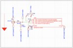
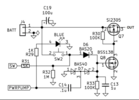
This is main schematic of the digital switch controlled by attiny10. The main idea was to connect button and mosfet to attiny and wake it up only when its needed. And after it woke up and turned on PCB, arduino will take control over mosfet using ONOFFMON . Attiny see it with ONOFFMON pin input and goes to deep sleep. Every time the button will be pressed, attiny immediately see that ONOFFMON and goes to sleep again.
Arduino on this pcb has 3.3v logic, because it connected to Lora, and lora shold be having only 3.3 logic. So that is why I had to do this trick with attiny. I want to make something like short press, than long hold until the PCB will woke up or shuts off like DJI.
1)The main idea is to make, on the first button press, attiny wakes up and immediatly opens mosfet.
2)Arduino powers on and check the button state and how long it was pressed.
3) if all ok, takes the control over mosfet, and sends high signal on pin, that is connected to the same signal line where attiny controls mosfet. (ONOFFMON).
4) ONOFFMON same pin connected to another pin of attiny, so it understands, when arduino is controlling mosfet to enter in to the deep sleep immideatly when it wakes up from the push button (because it connected also to the arduino pin as input)
5) To power off, arduino understands the specific button press and ONOFFMON becomes low.
attiny wakes up, because there was level change, sees that ONOFFMON is low and the button is holding. inside internal memory is written that the board is on, so i need to change level, and it turns off.
This is the idea that i thought that could work. Any suggestions? Maybe you tell me that i'am a total idiot. Or this schematic eventually can exist. Or there are some mistakes?
Any thoughts. I need to make somehow power on and power off from one push-button, that this button could be also used as input for arduino, and won't occupy a lot of space on PCB.
I actually did the same post here on reddit: https://www.reddit.com/r/arduino/comments/1emn33h
It is described probably a bit better. And got the response, that I have to use this schematic (last image).
but i also had some questions about that,
Pulsations should be on specific value? And what you think about if I implement this schematic in some commercial project. Like is it ok, or better to use something more advanced, or I'm safe?
Pwm is used to detect button at some point, right?
Any advises, thank you!