Sir Cmvalerius
Hopefully . . .
TOTALLY CLARIFIED, this time. . . .See bottom of page . . .
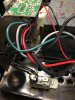
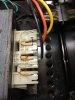
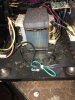
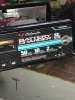
the white relay . . . . . . . is actually being a thermal, auto timeout and self reset overload breaker . . . .
View attachment 63421
Encountered on two different units, in past times.
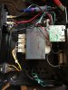
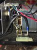
ALSO be sure to check out the electro-mechanical integrity of that . . .
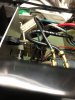
YELLOW CIRCLED . . . . pop rivet, as two dissimilar metals are being joined here and the total current of the charger passes thru it.
On mine, I additionally used a stranded 10 ga wire jumper to a terminal lug at the alum-i-ninny-yum-yum plate, with the other wire end soldered to the pcb pad.
FACTOID !
This full wave pulsating DC unit has no filtering . . . . .so don't expect some higher DC voltage reading without the battery connected.
Then, the connected battery will supply the "filtering" action and you will see the charging battery voltage incrementally increase as a charged condition is experienced.
Thaaaaasssit . . . .
73's de Edd . . . . .
View attachment 63422
.