USMC Jimmy
- Nov 1, 2009
- 4
- Joined
- Nov 1, 2009
- Messages
- 4
Hello,
I not sure if this is one of the best places to post this, but if it needs to be moved MODs, please do so.
Anyways, I just got back from my 2nd tour and before I left on the 2nd one, me and pops, he's no longer with us anymore, had built me a interface for my car, in the last move, I somehow misplaced the box I had it in.
I really wanted to comeback and enjoy our toy, but now that I can't find it.
Back to the point!!
So I know nothing about, this kind of work, but wanted to know if some kind person might he me out with this, I have worked for a few weeks on this and am getting really frustrated with this.
I still have a really long way to go on this, after he passed the bank just threw all his stuff away so I have limited DOC's and NO info on parts.
I have most of the parts figured out, but I lack a few this, KNOWLEDGE is this area.
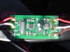
Here's a picture of it, and what I think most of the parts are, can you help out for a min???
The picture is from when he got it back from his buddy who made it for us.
#1] resistor 2001
#2] SS S or 55 5.. Is this a diode?
#3] Diode orange, silver stripe in the middle and a black band on the end. I know this is a Zener somethings or other..
#4] National Semiconductor 39AF LM78L 05ACM
#5] 35V 10uf
#6] 35V 10uf
#7] SS S or 55 5
#8] 12F629 (E3) 1/SN 0505
#9] resistor 2001
#10] Tantalum "Cream colored", not sure if that right
#11] Tantalum "Cream colored", not sure if that right
#12] 20.000M o5
#13] resistor 2001
#14] resistor 2001
Thanks you very much!!!
Sgt Jimmy
USMC
I not sure if this is one of the best places to post this, but if it needs to be moved MODs, please do so.
Anyways, I just got back from my 2nd tour and before I left on the 2nd one, me and pops, he's no longer with us anymore, had built me a interface for my car, in the last move, I somehow misplaced the box I had it in.
I really wanted to comeback and enjoy our toy, but now that I can't find it.
Back to the point!!
So I know nothing about, this kind of work, but wanted to know if some kind person might he me out with this, I have worked for a few weeks on this and am getting really frustrated with this.
I still have a really long way to go on this, after he passed the bank just threw all his stuff away so I have limited DOC's and NO info on parts.
I have most of the parts figured out, but I lack a few this, KNOWLEDGE is this area.
Here's a picture of it, and what I think most of the parts are, can you help out for a min???
The picture is from when he got it back from his buddy who made it for us.
#1] resistor 2001
#2] SS S or 55 5.. Is this a diode?
#3] Diode orange, silver stripe in the middle and a black band on the end. I know this is a Zener somethings or other..
#4] National Semiconductor 39AF LM78L 05ACM
#5] 35V 10uf
#6] 35V 10uf
#7] SS S or 55 5
#8] 12F629 (E3) 1/SN 0505
#9] resistor 2001
#10] Tantalum "Cream colored", not sure if that right
#11] Tantalum "Cream colored", not sure if that right
#12] 20.000M o5
#13] resistor 2001
#14] resistor 2001
Thanks you very much!!!
Sgt Jimmy
USMC