Something my Dad had built for me, he's no longer with us;(

USMC Jimmy

Nov 1, 2009
4
Joined
Nov 1, 2009
Messages
4
You can see the whole post over here, I think you should, that won't make me look that much of an a$$..lol

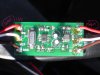
Anything will help, ID, PDF files, DATA sheets and etc.
I would be so thankful for anyones help on this.


#1] 2001
#2] SS S or 55 5
#3] Diode orange, silver stripe in the middle and a black band on the end.
#4] National 39AF LM78L ?5ACM
#5] 35V 10uf
#6] 35V 10uf
#7] SS S or 55 5
#8] 12F629 (E3) 1/SN 0505
#9] 2001
#10] Tantalum "Cream colored", not sure if that right
#11] Tantalum "Cream colored", not sure if that right
#12] 20.000M o5
#13] 2001
#14] 2001


Thanks

Sgt Jimmy
USMC
 

Attachments

  • board.jpg
    board.jpg
    91.6 KB · Views: 900

fzabkar

Oct 18, 2009
12
Joined
Oct 18, 2009
Messages
12
The LM78L05ACM (item #4) is a 5V regulator:

http://www.datasheetarchive.com/pdf-datasheets/Datasheets-20/DSA-386083.pdf

It supplies power to the Microchip PIC 12F629 "FLASH-Based 8-Bit CMOS Microcontroller" (item #8):

http://www.datasheetarchive.com/pdf-datasheets/Datasheets-19/DSA-360334.pdf

Diode #3 probably provides reverse polarity protection on the +12V supply input. It is probably a general purpose rectifier.

I suspect that #10 & #11 may be ceramic capacitors. Items #5 & #6 are obviously electrolytics.

Items 1, 9, 13, & 14 are probably 2.00K resistors. The end digit would be the multiplier.

Item #12 is a 20MHz crystal.

Items #2 & 7 appear to be transistors, but I'm not sure about this.

One possible candidate is a BSS138 N-channel logic level MOSFET:

http://www.fairchildsemi.com/ds/BS/BSS138.pdf

The function of the circuit would be defined by the code within the uP.
 

bobdole369

Nov 4, 2009
1
Joined
Nov 4, 2009
Messages
1
Most of this is support for the microchip PIC 12F629. In order to work it needs power. The diodes and caps and 7805 seem to be doing that, and the 20mhz crystal is needed for the PIC to run.

Unfortunately without knowing the program contained within the PIC 12F629 its very hard to tell what this does and how. Typically PIC's take inputs (such as a short to ground or +5V) and activate outputs (usually sinking to ground (i.e. supplying ground)) some PIC's do serial data stuff or even analog to digital or digital to analog conversions.
 

JMFahey

Jan 10, 2010
1
Joined
Jan 10, 2010
Messages
1
Hi USMC
Please tell us what's that board supposed to do.
What's your problem?: it doesn't work any more?
It acts funny?
Do you want to build another one for your little brother?
PICS are versatile multipurpose workhorses, maybe what it does is something simple that can be duplicated some other way.
Besides, that board looks commercial, please post a picture of the solder side, anything written there might ring a bell.
 
Top