Switching leds

AnalogKid

Jun 10, 2015
3,050
Joined
Jun 10, 2015
Messages
3,050
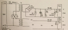
The trick I described in post #14 for TR2 is the same thing being done by TR1, D7, and D8, and the opto.

ak
 

Nickb1969

Aug 28, 2016
19
Joined
Aug 28, 2016
Messages
19
So if I am not making sense. These are the two original circuit diagrams.
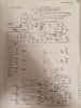
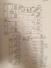
IMG_1699.JPG IMG_1700.JPG

This is the original board with 4 channels.
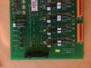
IMG_1694.JPG

This is original power supply/relay board
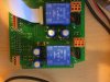
IMG_1696.JPG

I have lifted part of the circuit to create this as a single channel board. Not fully assembled and only prototype.
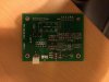
IMG_1697.JPG

The is then an smps and a plug in led board. 1 to 4 of these boards plug into a motherboard.

I am basically 90% there, the led issue is sorted for the next prototype with extra components added. I am just struggling with the voltage across the relay coil.

When I get home in a week I will post the pcb files.

Thanks for your patience.
 

CDRIVE

Hauling 10' pipe on a Trek Shift3
May 8, 2012
4,960
Joined
May 8, 2012
Messages
4,960
Thanks that's a whole lot better. It also clarifies what those rectangles are scattered throughout those schematics. Apparently two way jumper headers but I've never seen them drawn like that. Especially without at least one of the jumper positions connected.

Going for a bike ride but AG isn't. He'll probably iron out your issue before I return.

Chris
 
Last edited:

CDRIVE

Hauling 10' pipe on a Trek Shift3
May 8, 2012
4,960
Joined
May 8, 2012
Messages
4,960
I have lifted part of the circuit to create this as a single channel board. Not fully assembled and only prototype.


I am basically 90% there, the led issue is sorted for the next prototype with extra components added. I am just struggling with the voltage across the relay coil.

Thanks for your patience.
(1) Earlier you stated that the V+ to the relay is measuring 8V. That's an oddball voltage for standard relay. Have you checked the power supply output voltage with and without load? You do realize that what appears to be the power supply...
upload_2016-10-2_13-6-38.png

is feeble?!!!

(2) What's the relay specs? Your Relay Board photo doesn't seem to include the relay.

(3) When posting voltage measurements always make them from circuit GND. This way there's no ambiguity at this end of the conversation.

(4) Earlier I made comment I made mention of what I thought to be jumper headers but after looking closely at the board photos I now realize that those rectangles are Dip Switches. What dip sh!t drew and labeled them like that? I know it wasn't you! To be honest when I viewed the first schematic you posted I thought that they were some goofy finger (touch) pads. In other words I didn't know what your project was all about. We get a lot of off the wall stuff here. I had no clue that they were dip switches.

Chris
 

Nickb1969

Aug 28, 2016
19
Joined
Aug 28, 2016
Messages
19
Hi Chris,

The voltage across the relay should be 12v. On the original unit as pictured it is 12v. On my new board the voltage is down to 8v. The is 12v in the circuit and the smps being used for test is 35w so plenty big enough.

This is where I may loose you. When jumpering EW to C then the relay have 8v across the coil when energised and 3.8v across the coil when de-energised. It should be 12v energised 0v de-energised. The only thing I can think of is that I has something wrong on my board compared to the original.

The original boards and schematics has solder pads and not dip switches, I changed this for dip switch as I added an extra resistor. That side of the circuit words well.

The relay is a DS2E-S-12 high sensitivity relay. 12vdc coil. 18mA I think.

All the schematics posts are from the original boards and these have been in service for many years. I have replaced the power supply with a caged SMPS, all the solder pads with jumpers and dip switches.

I know I have something wrong on my board because I am getting this 8v at the relay coil. I don't know how to describe it is almost like 12v is getting to the relay coil but 3.8v is getting left behind.

When I get home I will set it up a video it show the old unit and the new one.
 

CDRIVE

Hauling 10' pipe on a Trek Shift3
May 8, 2012
4,960
Joined
May 8, 2012
Messages
4,960
Hi Chris,

The voltage across the relay should be 12v. On the original unit as pictured it is 12v. On my new board the voltage is down to 8v. The is 12v in the circuit and the smps being used for test is 35w so plenty big enough.

This is where I may loose you. When jumpering EW to C then the relay have 8v across the coil when energised and 3.8v across the coil when de-energised. It should be 12v energised 0v de-energised. The only thing I can think of is that I has something wrong on my board compared to the original.

The original boards and schematics has solder pads and not dip switches, I changed this for dip switch as I added an extra resistor. That side of the circuit words well.

The relay is a DS2E-S-12 high sensitivity relay. 12vdc coil. 18mA I think.

All the schematics posts are from the original boards and these have been in service for many years. I have replaced the power supply with a caged SMPS, all the solder pads with jumpers and dip switches.

I know I have something wrong on my board because I am getting this 8v at the relay coil. I don't know how to describe it is almost like 12v is getting to the relay coil but 3.8v is getting left behind.

When I get home I will set it up a video it show the old unit and the new one.
This is a painful thread because our eyes can't rely on anything we see posted. Especially the schematics! I'd say this thread is driving me to drink but I really don't need an excuse to do that.

Check the Gate voltage of the FET relay driver when On an OFF (from GND) and post what you measure there.

Chris
 

Nickb1969

Aug 28, 2016
19
Joined
Aug 28, 2016
Messages
19
I am sorry that I am unable to explain any better and that you don't understand what I am saying. I will not bother you any more. I am not an electronics person but I will figure it out some how, I always do. I think posting more will only make it more confusing. I know what I see and what I measure, I just don't understand why I am getting these readings and how to solve it. There is a difference somewhere between the original equipment and my version, that is causing the problems. If I do find it I will update the thread as a matter of good manners.
 

CDRIVE

Hauling 10' pipe on a Trek Shift3
May 8, 2012
4,960
Joined
May 8, 2012
Messages
4,960
Nick, you must be relatively young and don't deal with cantankerous old farts much. Some of us simply regard it as a rite of passage. Please don't confuse my gripes with unwillingness to help.

Nick, please measure the Gate voltage of the FET that's driving the relay coil. Do this while the relay is energized and de-energized. Then post your measurements. Also post the PN of the FET.

Chris
 

Nickb1969

Aug 28, 2016
19
Joined
Aug 28, 2016
Messages
19
Hi Chris,

I will be back home in a couple of day. Been quite a busy week as I am moving my mum back to UK from Spain.

I already know the answer to your question and been trying to learn some things whilst lying awake a 3am.

The voltage is 8.8v, this all comes back to the question on the 4.7k resistor.

This is about my lack of understanding and nothing else. These are the facts on this part of the circuit and I think R14 is wrong.

12.3v to R14
R14 feeds TR1 which is a zvn2110a mosfet
TR1 feeds the relay
Relay is a DS2E-S-12v. So 12v coil with 720 ohm coil resistance. 16.7mA

Current R14 value is 4.7k
Correct value is ?????

On the original circuit R14 also fed the opamp but that has been removed from the new version.
 

CDRIVE

Hauling 10' pipe on a Trek Shift3
May 8, 2012
4,960
Joined
May 8, 2012
Messages
4,960
On the original circuit R14 also fed the opamp but that has been removed from the new version.
On the original circuit R14 is not also feeding an OpAmp as you say. It's feeding the LED input side of an OptoIsolator through Diode D8. The output side of that Opto is a JFET configured as a Source Follower. It feeds or did feed (?) the inputs of logic gates.

Chris
 
Top