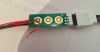
5V 'between' the pads does not do much good as that tells us that it is most likely 5V logic, but does not tell us if the IC that is receiving the signal is waiting to get pulled to 0V, or 5V. This does make a difference.
From the close-up you have provided, it looks as thought the inner ring has 5V on it. The outer ring has 0V on it. This leads me to believe, but not guarantee that the chip (technical term
")
) has a 5V pull-up resistor, and is pulled low when the button is pushed. (I base this on the fact that the outer ring is common on all 3 buttons, and has a very large trace. This does make a difference and is very important, as it will mean the difference between connecting 0V to the middle pad, or 5V if you make your own circuit to supply the signal.
The LED in the switch only lights up when the switch is pushed.
What is the required supply voltage for the LED?
Can you please confirm that the contacts on either side are for the LED. (I could only clearly see one side in the pictures)
The LED in series with the pad connection idea did not work.
I do not recall, or see that idea being presented by you or myself. (Unless I missed it.. it does happen)
If the LED
only lights when the button is pushed by itself, then all you need to do is provide the appropriate source across the leads on either side of the button and that half is done. (Waiting confirmation on required supply for the LED)
The two remaining connections on the switch (bottom and back) will be directly connected to the wires you have soldered to the pads already.
That switch appears to be two separate distinct halves which should make this easy.