Understanding if this circuit

Rajinder

Jan 30, 2016
568
Joined
Jan 30, 2016
Messages
568
Hi All,
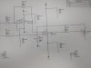
I was wondering if somebodycan give me some help in understanding this circuit. The first stage is a inverting amplifier stagevwith gain of -1. If I put in 0.5V I then get -0.5V.
This goes into a second stage which the N channel FET is in the feedback loop of the opamp, It is a negative constant current. The opamp adjusts the gate drive to keep its inputs the same, the output is then Vin / 10K resistor.
My question is that the FET drain is at 0V, the source will be at negative potential. Is this why this circuit works?
I always thought the Drain should be more positive than Source also the gate needs to be higher than Source. So can this work as Drain is higher I.e. 0V than the negative source ? As long as the gate is greater than threshold of FET. Does this work in the triode or linear region if the opamp? Like a potentiometer?
I look forward to hearing from you.
Best regards,
Rajinder
 

Attachments

  • IMG_20160513_155420071.jpg
    IMG_20160513_155420071.jpg
    105.9 KB · Views: 75

Rajinder

Jan 30, 2016
568
Joined
Jan 30, 2016
Messages
568
Hi, sorry my apologies. The output is the other end of R60 the 10K resistor. Si my thinking was that the opamp keeps inputs the same. Hence the voltage at the top end of R60 will be same as Vin. Therefore I = -Vin/R60.
I was not sure of the Drain at 0V and Source at negative. I think it is in triode mode but not 100% sure.
Thanks.
Rajinder
 

Rajinder

Jan 30, 2016
568
Joined
Jan 30, 2016
Messages
568
R7 is fed from a inverting stage opamp with gain of -1 using 100k at input and 100k at output stages.
The other end of the opamp I switch
Different value resistors from 10k to 1m to give different negative currents.
 

davenn

Moderator
Sep 5, 2009
14,470
Joined
Sep 5, 2009
Messages
14,470
The output is the other end of R60 the 10K resistor.

No, that is tying IN- to a -5V rail via R60
there is no output there


you have given far too little info to let anyone help you
show us the whole circuit ... ie. what comes before R7 and R8

where did this circuit come from ? It really doesn't make any sense
 
Last edited:

Rajinder

Jan 30, 2016
568
Joined
Jan 30, 2016
Messages
568
R8 is fed from a inverting opampnwith gain if -1. R7 has various resistors switched in to give me different currents. This is a negative constant current circuit.
the inverting amplifier sends a voltage. To the pin of the opamp pin 3, the FET is in the loop and ensures that pin2 of opamp is at same potential as pib 3. Hence it is a programmable negative constant current. My question is on N channel enhancement FER, can you put drain to 0V and source to negative. Since the drain is more positive than the source, should thus circuit work?
 

(*steve*)

¡sǝpodᴉʇuɐ ǝɥʇ ɹɐǝɥd
Moderator
Jan 21, 2010
25,510
Joined
Jan 21, 2010
Messages
25,510
My question is on N channel enhancement FER, can you put drain to 0V and source to negative. Since the drain is more positive than the source, should thus circuit work?

Sure.
 

davenn

Moderator
Sep 5, 2009
14,470
Joined
Sep 5, 2009
Messages
14,470
R7 has various resistors switched in to give me different currents. This is a negative constant current circuit.
the inverting amplifier sends a voltage

constant current for what purpose ?
sends a voltage to where ? .... there is no output


Dave
 

(*steve*)

¡sǝpodᴉʇuɐ ǝɥʇ ɹɐǝɥd
Moderator
Jan 21, 2010
25,510
Joined
Jan 21, 2010
Messages
25,510
I'm pretty sure the input is the output, but as you said, it would be great to see more of the schematic (to the left). If I wanted to present a puzzle I'd probably cut it off there too :)
 

Rajinder

Jan 30, 2016
568
Joined
Jan 30, 2016
Messages
568
Hi all,
Sorry but i will post the complete schematic today. My apologies.
Best regards,
Rajinder
 

Rajinder

Jan 30, 2016
568
Joined
Jan 30, 2016
Messages
568
Hi here is the complete diagram.
I have shown the output resistor that connects to the input of my CO alarm.
I think I can have the drain at 0V, which isore positive than the negative source and the gate is also positive wrt source.
Best regards,
Rajinder

IMG_2016051.jpg
 
Last edited by a moderator:
Top