Yes, your diagram in post #28 is what I suggested. I was hoping it would work...
Here is an explanation of Tomi Engdahl's circuit from post #10.
Horizontal and vertical sync signals from the VGA card are processed separately in the two gates connected to R1/C1 and R2/C2.
The resistor and capacitor detect the polarity of the signal, and the gate conditionally inverts the signal.
The result is that the outputs (pins 3 and 6) are always active high, regardless of the polarity of the signals at the video card. It's a clever trick.
An active high sync signal is normally low, and goes high for a short time at the start of each line (for horizontal sync) or field (for vertical sync).
So if you test pins 3 and 6 with the VGA card plugged in, you should see a normally low signal that pulses high briefly. The high pulse is the sync pulse.
The third gate combines the horizontal and vertical sync signals into a combined sync signal which is also active high. The logic here is not ideal, because during the vertical sync pulse, the horizontal sync pulses are actually inverted and the monitor will trigger from the wrong edge. This might possibly be a problem if the monitor is fussy about the signal. It's not easy to fix though.
So at the output of the third gate, both horizontal and vertical sync are positive. The fourth gate just inverts the active high combined sync signal, so it's normally high and pulls low for the sync pulses.
I don't know why the monitor is reporting positive horizontal sync with that circuit.
Because of the characteristics of the LSTTL output, pin 11 pulls low (down to 0V) strongly, but does not pull high strongly. So effectively it forces the sync pulses onto the green video signal.
Your true sync-on-green signal in post #23, that works with your monitor, has a positive video signal between about 0.3V (the black level) and 0.9V (maximum green), and negative sync pulses between 0.0V and 0.3V.
Your VGA card's video signals in post #19 appear to have their black level at 0.0V and peak around 1.0V.
My Schottky diode suggestion was supposed to work like this:
If a forward bias is applied to a Schottky diode, it drops typically about 0.3V (anode positive). My circuit was supposed to add 0.3V to the VGA card's video signal, to shift the black level up to about +0.3V (like in post #23). The gate would provide the bias for the diode when the gate output was high, and when the gate output was low, it would pull the outgoing video signal down to 0V, creating the negative sync between 0.0V and 0.3V.
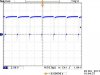
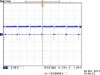
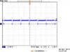
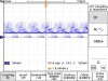
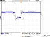
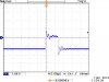
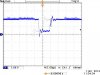
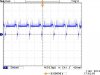
I can't really tell much from the scope traces in post #29. You need to use a slower timebase - say 20 µs per division. Those traces just show one horizontal sync pulse.
Don't bother reversing the diode. You had it right the first time. I don't think picture 4 looks any better than the others.
Try taking a scope trace of the green+sync output WITHOUT the monitor connected. That might tell me something.