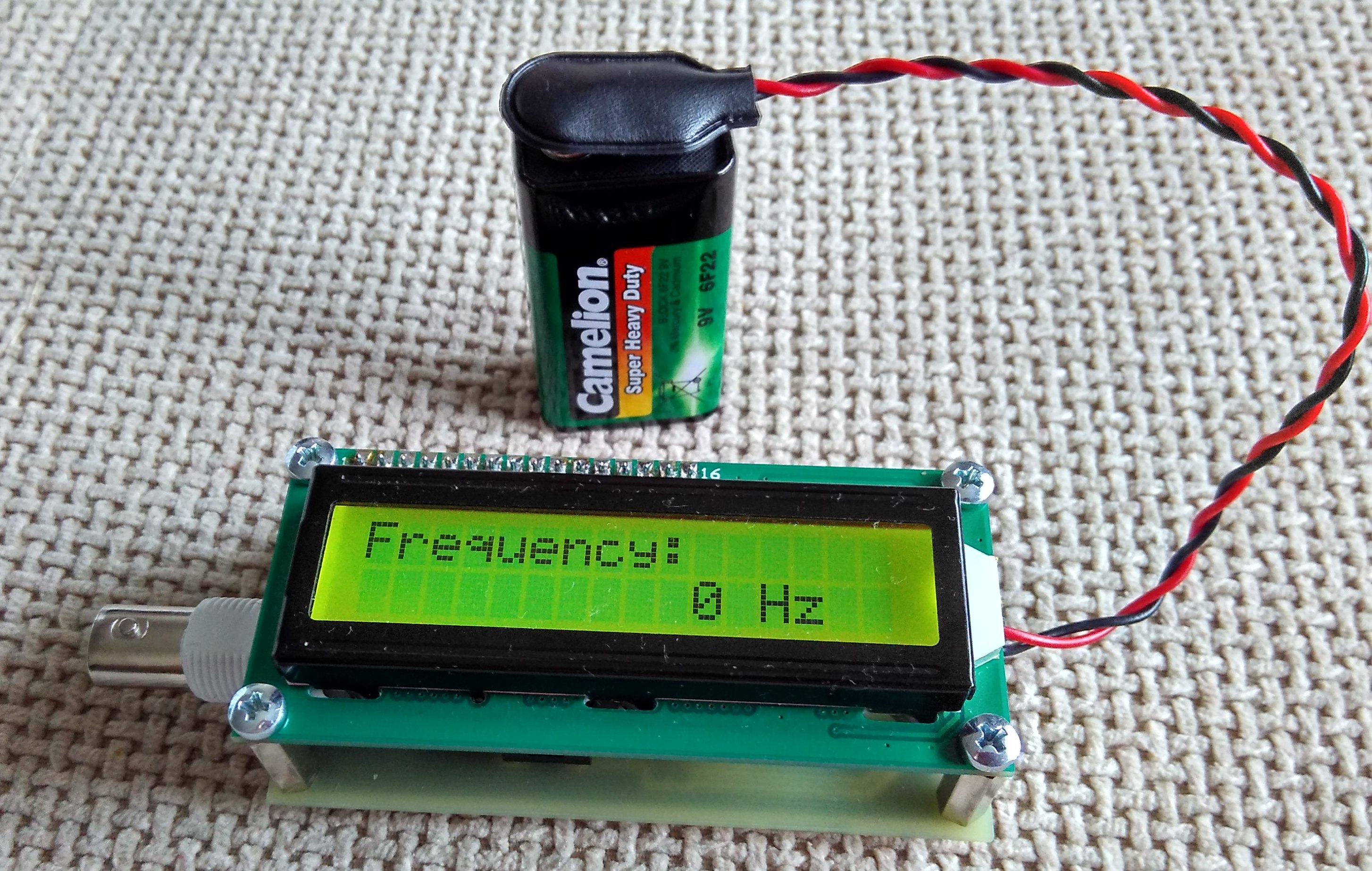
100MHz frequency counter with PIC16F628A – LCD Display
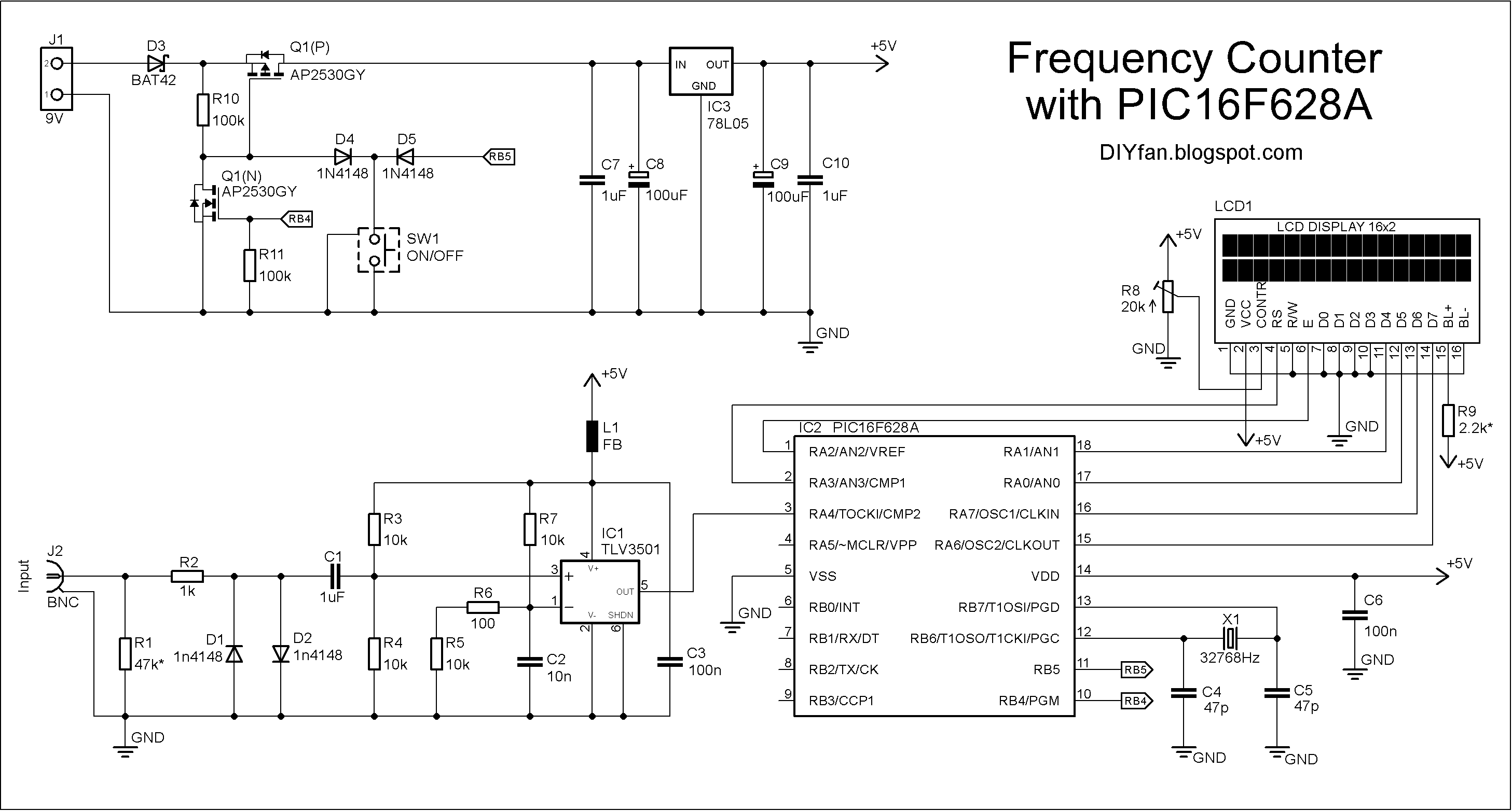
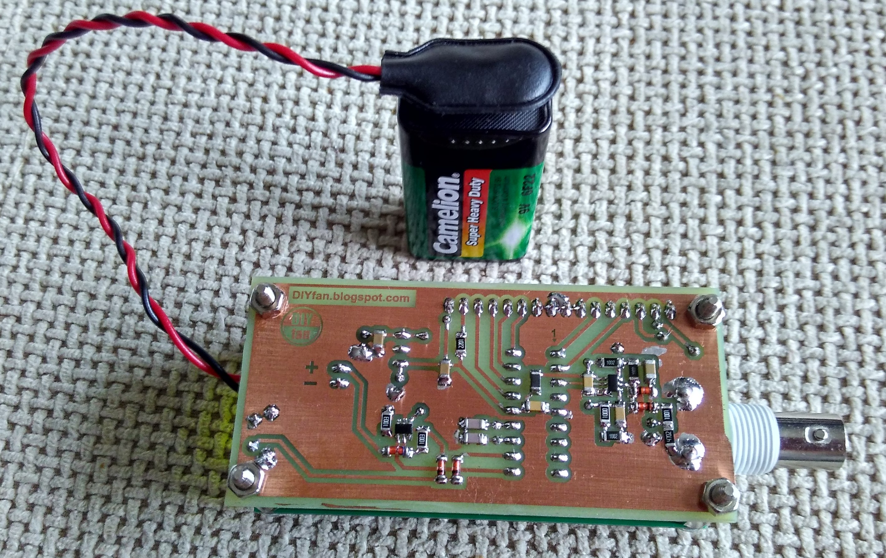
This project shows how to build a very simple yet very useful tool that every DIY enthusiast should have in his lab: a 100MHz+ frequency counter. The schematic is fairly simple and straightforward and uses a PIC16F628A microcontroller for measuring frequency and a high speed comparator for signal amplification and conditioning.
This project shows how to build a very simple yet very useful tool that every DIY enthusiast should have in his lab: a 100MHz+ frequency counter.
The schematic is fairly simple and straightforward and uses a PIC16F628A microcontroller for measuring frequency and a high speed comparator for signal amplification and conditioning.
The microcontroller uses its internal 4MHz oscillator for the CPU clock. Timer1 uses an external crystal resonator (watch crystal) with 32768Hz frequency for setting the 1 second time base.
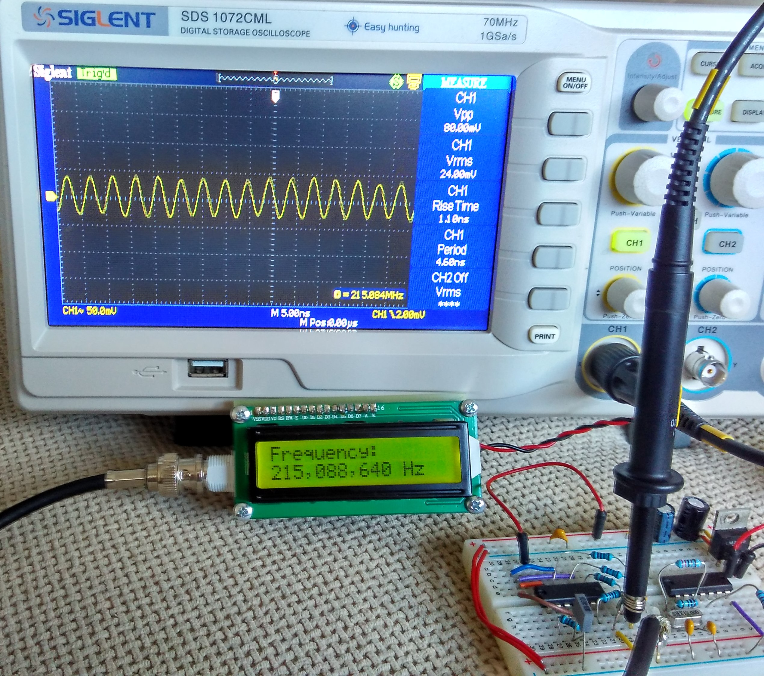
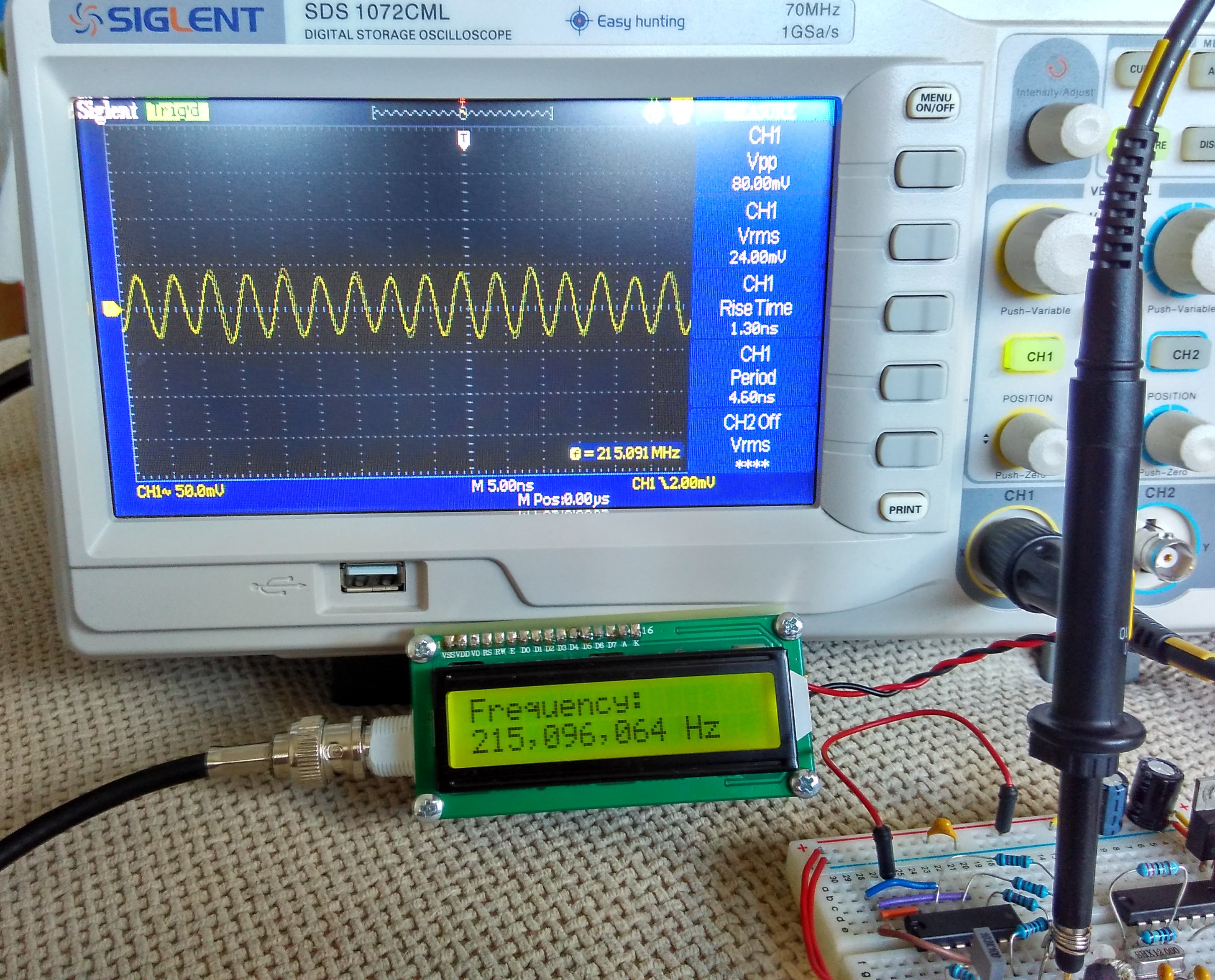
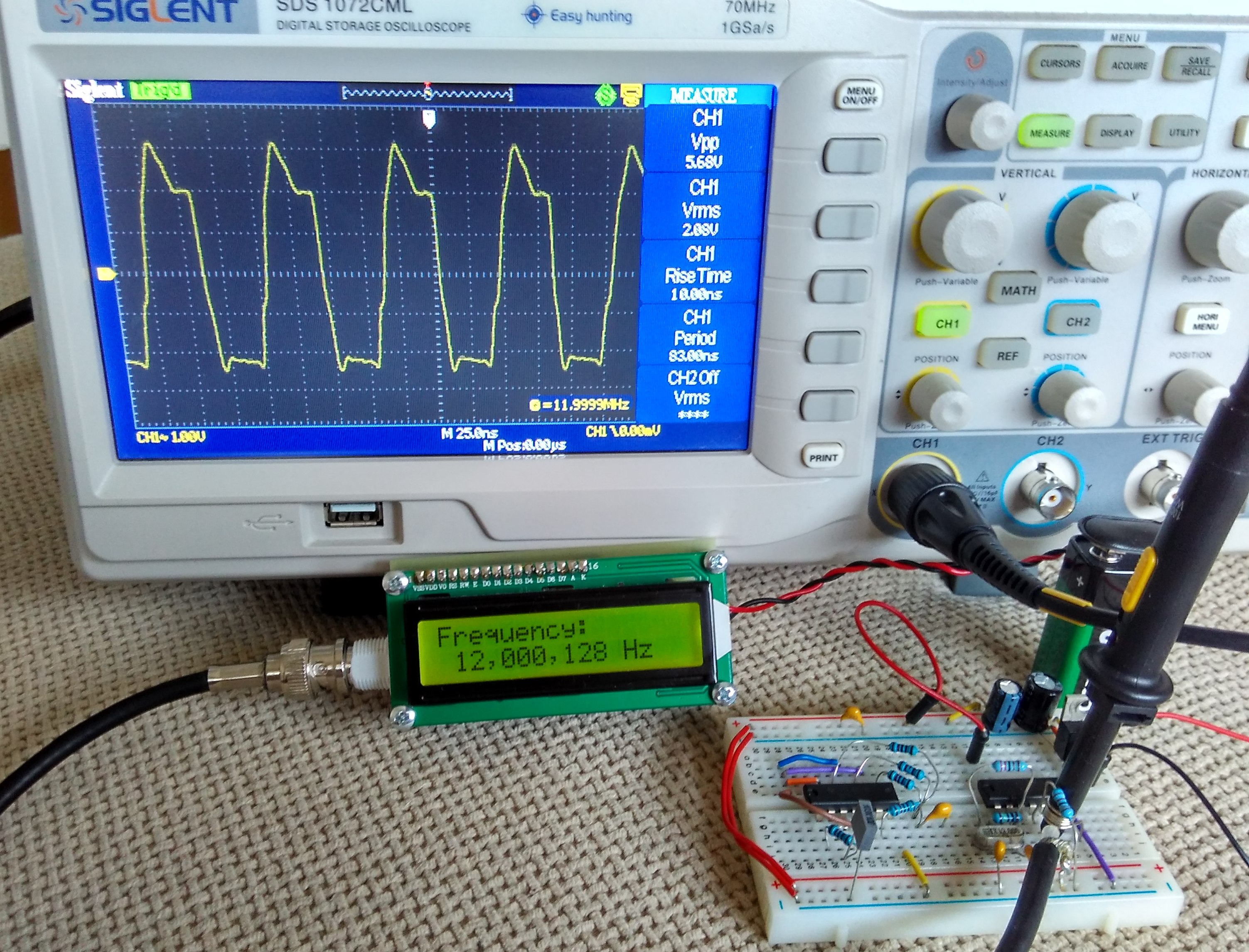
Timer0 is used to count the input signal at pin RA4.
The max frequency of Timer0 is 1/4 of the CPU clock which is 1MHz, but there is internal prescaler and it can be set from 1 to 256. In theory this can allow the input signal to be up to 256MHz. On the other hand, in the datasheet of 16F628A there is a requirement for the input pulse at RA4 to be with minimum width of 10ns which is 100MHz frequency. So the maximum frequency can be between 100Mhz and 256MHz. I checked with two different PIC16F628A and they easily go over 200Mhz barrier.
In order to achieve the maximum possible resolution, the input signal is probed for 0.125 seconds and the prescaler value is computed accordingly. This way when input frequency is below 1Mhz the resolution will be 1Hz.
The most important part for the accuracy of the frequency counter is the time base setting circuit – crystal resonator X1 and capacitors C4 and C5. C4 and C5 values can be between 33pF and 62pF and the crystal frequency can be fine tuned with them.
The input of the schematic is feed through a high speed comparator. In order to switch with 100+ Mhz frequency the comparator must have propagation delay bellow 5ns. In this schematic I used Texas Instruments TLV3501 with 4.5ns delay. This was cheapest high speed comparator I was able to find (2.5 euro).
The two inputs of the comparator are set at about 1/2 of power supply voltage with 15-25mV difference between them so any AC signal with higher voltage will start switching the comparator.
If there isn’t input signal the output of the comparator stays low. If we connect a signal source to the positive input, when the signal goes over +20mV the comparator switches high (5V), when signal goes bellow +20mV comparator switches back to 0V. So whatever signal we fed to the input, the output is square wave 0V-5V with the same frequency as the original signal.
The output of the comparator is fed directly to the RA4 pin of the microcontroller.
The input is protected with 1k resistor and two diodes limiting the voltage to ±0.7 V. The input impedance for low frequencies is equal to R1 – 47k. For VHF range maybe it is good idea to replace it with 50 Ohm value.
The schematic can be powered by 9V battery or any other DC voltage from 7V to 15-20V. LM78L05 or LM2931-5.0 IC is used for regulating the voltage down to 5V. There is simple soft ON/OFF circuitry with a dual P- and N-MOS transistor. When button is pressed the P-MOS transistor is switched on and the microcontroller is powered and its first instruction is to set RB4 high which switch the N-MOS transistor on and the power stays on. If the button is pressed again RB5 goes low and the microcontroller sets the RB4 low and this way switch the power off. The microcontroller also auto switch the power off after a certain amount of time (3min 40sec).
The schematic have fairly low power consumption – with no input signal the supply current is 7-8mA and goes up to 20mA with 200+MHz input signal. If the display is too dark, the back light can be adjusted by decreasing the value of the R9 resistor. This of course will increase the current consumption.
The program for the microcontroller is written in C and is compiled with MikroC for PIC
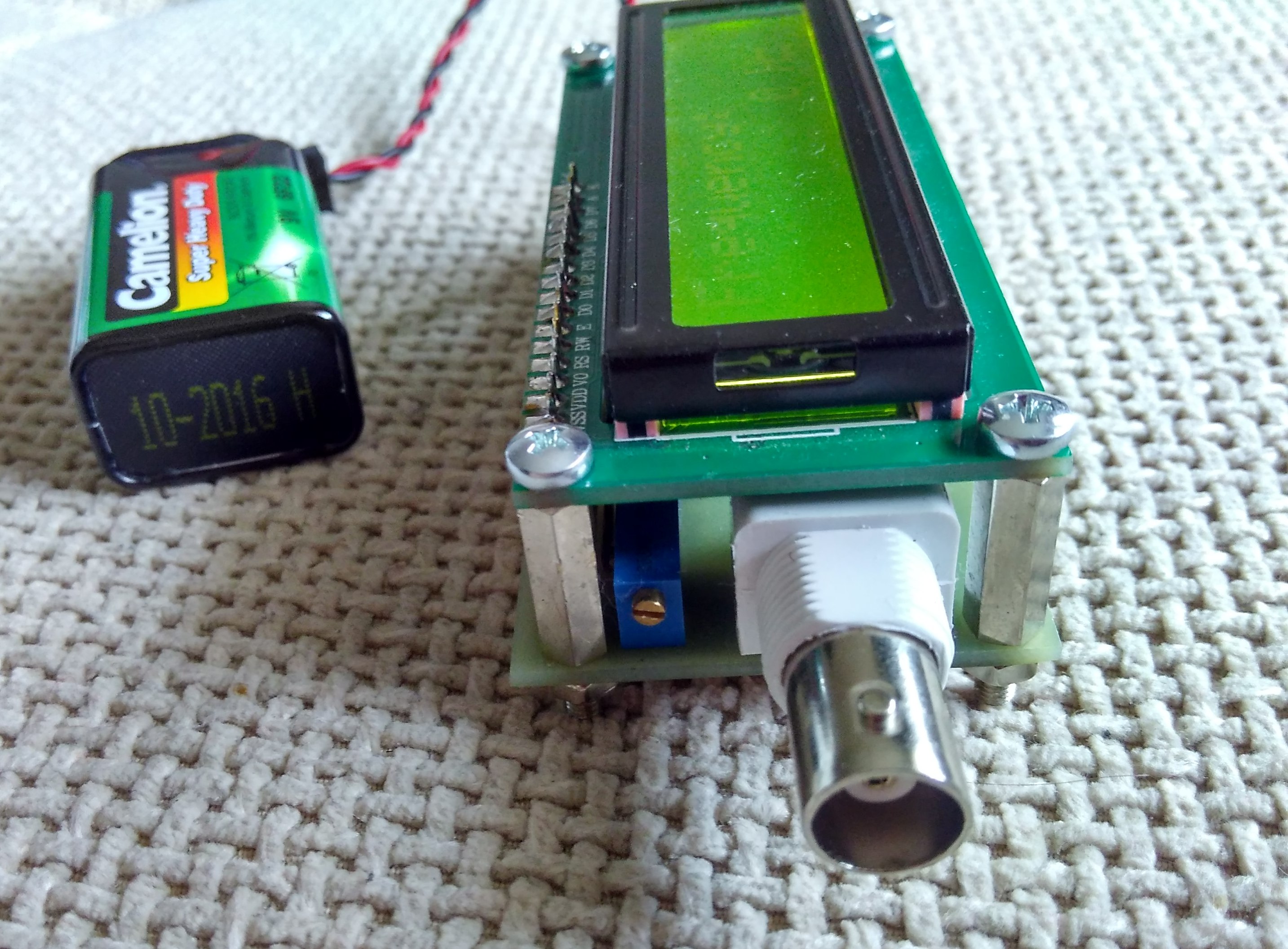
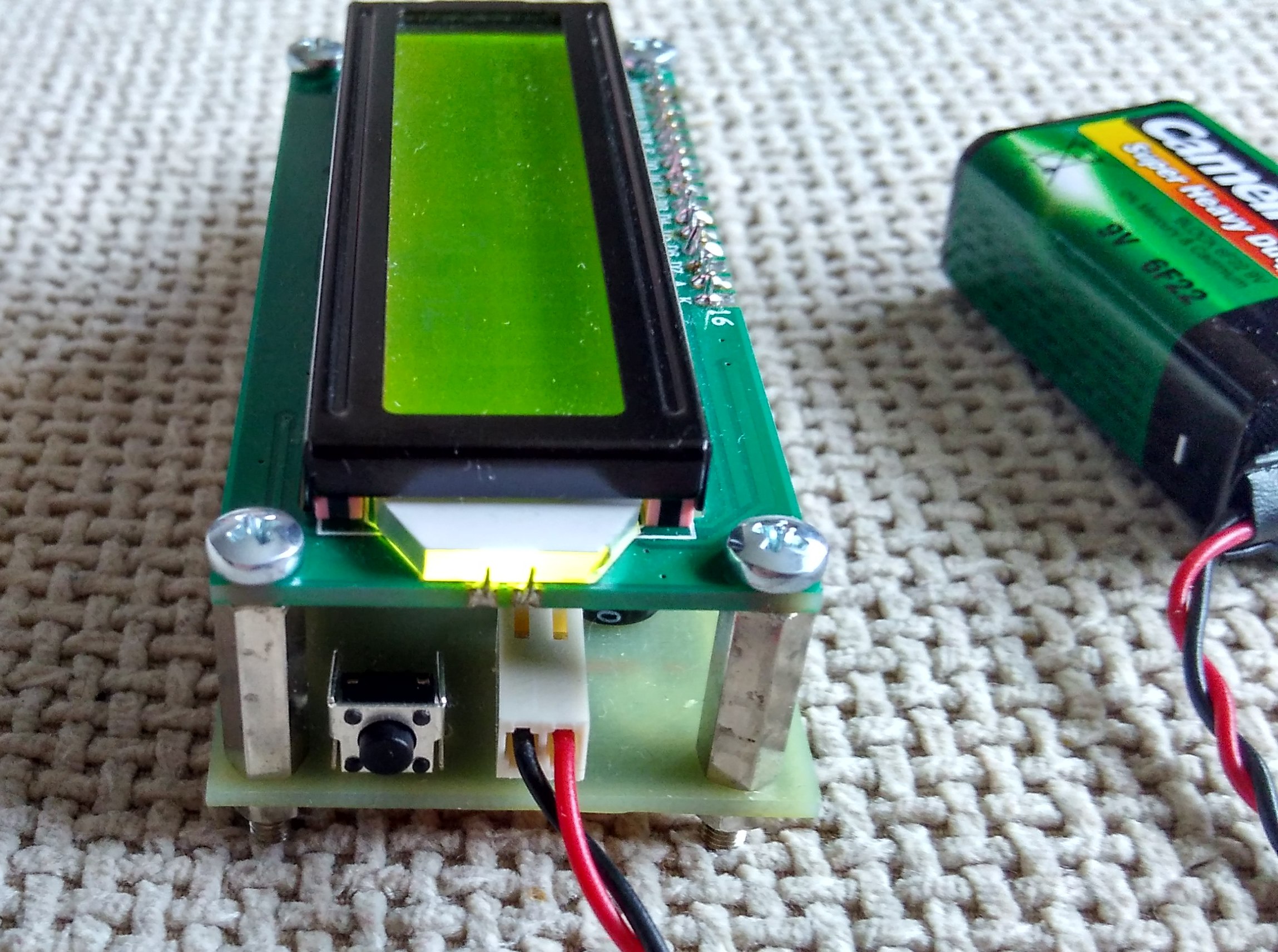
Schematic
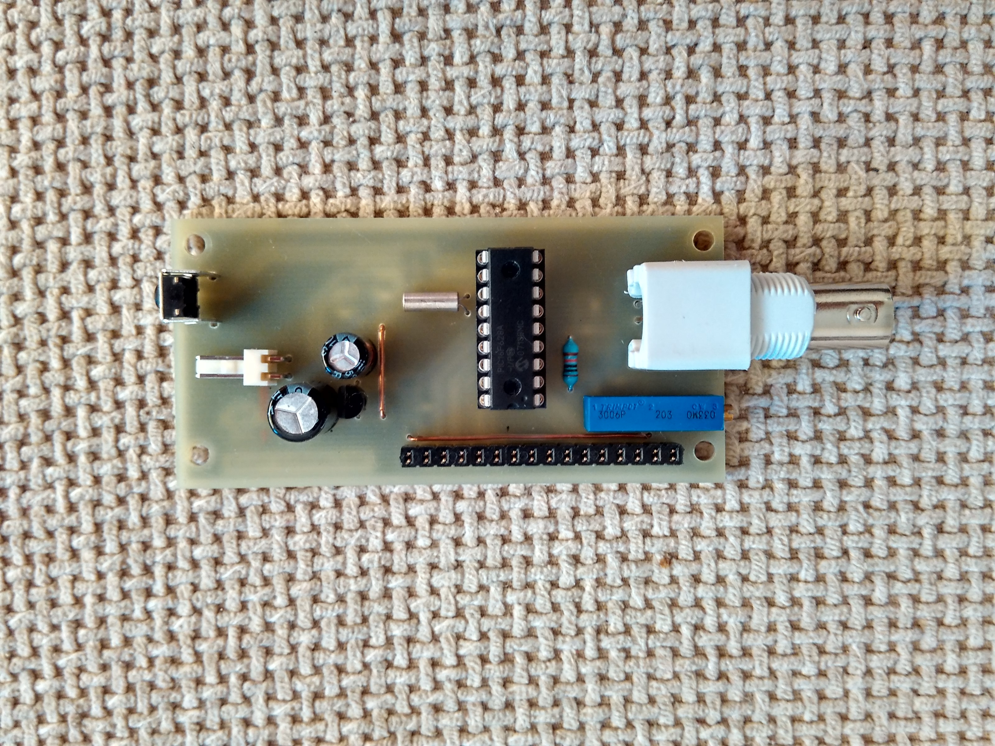
Photos
can i expect a copy of ther link where from i can get the souce code and .hex file please
mvssarma@gmail.com
Finally u could manage the code as i had ince downloaded , way back in 2017. It was lying in some removed hdd.
I am unable to attch it to support other suffering with similar problems
Any one needy of original wrking code cam mail to me
mvssarma(at) gmail
Hello
Please Send Firmware Code And PCB Drawings, Project
please reach my google account on mvssarma, i can send files that are working. ATB
Ibdid notbhear from you.
hi mixos,
should i assume that there is no comrehensive c code or a compiled .hex file what does power switching with button and measure the frequency? we are diverted to another site where their project doent have the power switching.
many a time I write a message , perhaps it is going uneard.
then why not we remove the project or let some old membmer up load the files here.
i find “scribed” is making money showing an old page of electronicslab.com, where the concerned files are shown. But unless the credit card is linked for monthly recovery or callit payment they dont permit any access.
please spare few minutes and try to respond.
regards
mvs sarma
a retd telecom guy at 81.
CADE O ARQUIVO HEX ? . COLOQUE ELE AÍ PÔ
have working file i tested. reach me on my google mail as mvssarma
Dear mixos,
i can I attach a working souce code and hex files for this 100mhz lcd frequency counter. I have one tested working. it was downloaded way back in 2017
Dear mixos
Is there any way i can upload a file of working c code in the messages.
Regards
Sarma vu3zmv