Frequency To Voltage Converter (Tachometer) – Variable Reluctance Magnetic Pickup to Voltage Converter
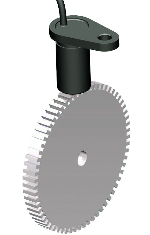
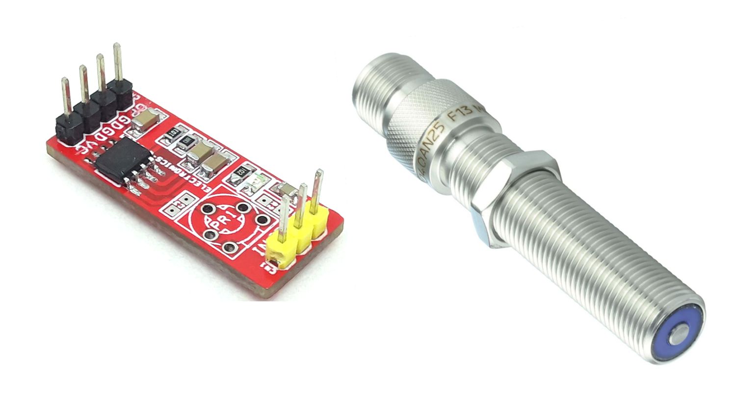
The circuit shown here is a frequency-to-voltage converter that can be used in many applications. This is a signal conditioner for Variable Reluctance Magnetic Pickup Sensor used in engines or machines to detect the speed by sensing gears' teeth.
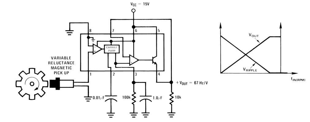
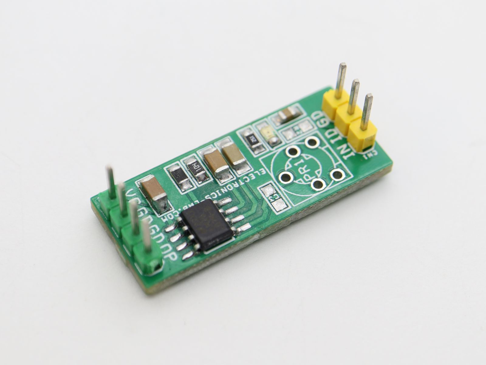
The circuit shown here is a frequency-to-voltage converter that can be used in many applications. This is a signal conditioner for Variable Reluctance Magnetic Pickup Sensor used in engines or machines to detect the speed by sensing gears’ teeth. The input signal level is 20mV to 28V. The circuit provides 1V (67Hz/Volt) when the input frequency is 67Hz with a 15V power supply. The maximum input frequency is 1Khz. The project was built using LM2907N-8 IC, refer to the datasheet of the chip for more information and various configurations. CN1 connector is provided to connect the sensor or input signal. D1 power LED, CN2 Power input, and Voltage output. Use the formula below to calculate voltage output from the desired frequency input.
VOUT = fIN × VCC × R3 × C4
The LM2907 series of tachometer circuits are designed for minimum external part count applications and maximum versatility. To fully exploit its features and advantages, first examine its theory of operation. The first stage of the operation is a differential amplifier driving a positive feedback flip-flop circuit. The input threshold voltage is the amount of differential input voltage at which the output of this stage changes state. Two options (8-pin LM2907 and LM2917) have one input internally grounded so that an input signal must swing above and below ground and exceed the input thresholds to produce an output. This is offered specifically for magnetic variable reluctance pickups which typically provide a single-ended AC output. This single input is also fully protected against voltage swings to ±28 V, which are easily attained with these types of pickups. The differential input options (LM2907, LM2917) give the user the option of setting his input switching level and still having the hysteresis around that level for excellent noise rejection in any application. Of course, to allow the inputs to attain common-mode voltages above ground, input protection is removed and neither input should be taken outside the limits of the supply voltage being used. It is very important that an input not go below ground without some resistance in its lead to limit the current that will then flow in the epi-substrate diode. Following the input stage is the charge pump where the input frequency is converted to a DC voltage. To do this requires one timing capacitor, one output resistor, and an integrating or filter capacitor. When the input stage changes state (due to a suitable zero crossing or differential voltage on the input) the timing capacitor is either charged or discharged linearly between two voltages whose difference is VCC/2. Then in one-half cycle of the input frequency or a time equal to 1/2 fIN the change in charge on the timing capacitor is equal to VCC/2 × C1.
Features
- Operating Supply 15V DC
- Output 67Hz/Volt (67Hz = 1Volt)
- Maximum input Frequency 1Khz
- Ground Referenced Tachometer Input Interfaces Directly with Variable Reluctance Magnetic Pickups
- Ground-Referenced Tachometer is Fully Protected from Damage Due to Swings Above VCC and Below Ground
- Output Swings to Ground for Zero Frequency Input
- Frequency Doubling for Low Ripple
- Input Signal Level 20mV to 28V
- PCB dimensions: 31.12 x 12.86 mm
Applications
- Variable Reluctance Magnetic Pickup to Voltage Converter
- Sound Signal to Voltage Converter
- Speedo Meter
- Under or Over Speed Sensing
- Touch Sensor
- Frequency to Voltage Converter
Schematic
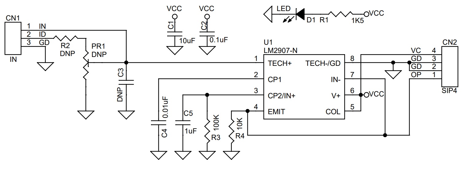
Parts List
| NO | QNTY | REF | DESC | MANUFACTURER | SUPPLIER | PART NO |
|---|---|---|---|---|---|---|
| 1 | 1 | CN1 | 2 PIN MALE HEADER PITCH 2.54MM | WURTH | DIGIKEY | 732-5315-ND |
| 2 | 1 | CN2 | 4PIN MALE HEADER PITCH 2.54MM | WURTH | DIGIKEY | 732-5317-ND |
| 3 | 1 | C1 | 10uF/25V SMD SIZE 1206 | MURATA/YAGEO | DIGIKEY | |
| 4 | 1 | C2 | 0.1uF/50V SMD SIZE 0805 | MURATA/YAGEO | DIGIKEY | |
| 5 | 3 | PR1,R2,C3 | DNP | |||
| 6 | 1 | C4 | 0.01uF/50V SMD SIZE 1206 | MURATA/YAGEO | DIGIKEY | |
| 7 | 1 | C5 | 1uF/25V SMD SIZE 1206 | MURATA/YAGEO | DIGIKEY | |
| 8 | 1 | D1 | LED SMD SIZE 0805 | LITE ON INC | DIGIKEY | 160-1427-1-ND |
| 9 | 1 | R1 | 1K5 5% SMD SIZE 0805 | MURATA/YAGEO | DIGIKEY | |
| 10 | 1 | R3 | 100K 5% SMD SIZE 0805 | MURATA/YAGEO | DIGIKEY | |
| 11 | 1 | R4 | 10K 5% SMD SIZE 0805 | MURATA/YAGEO | DIGIKEY | |
| 12 | 1 | U1 | LM2907N-8 | TI | DIGIKEY | LM2907N-8/NOPB-ND |
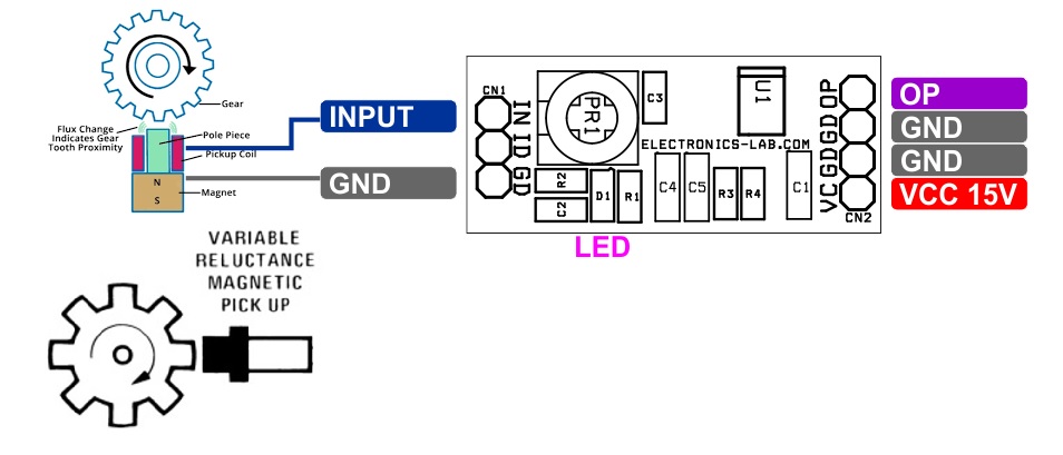
Application Diagram
Connections
Gerber View
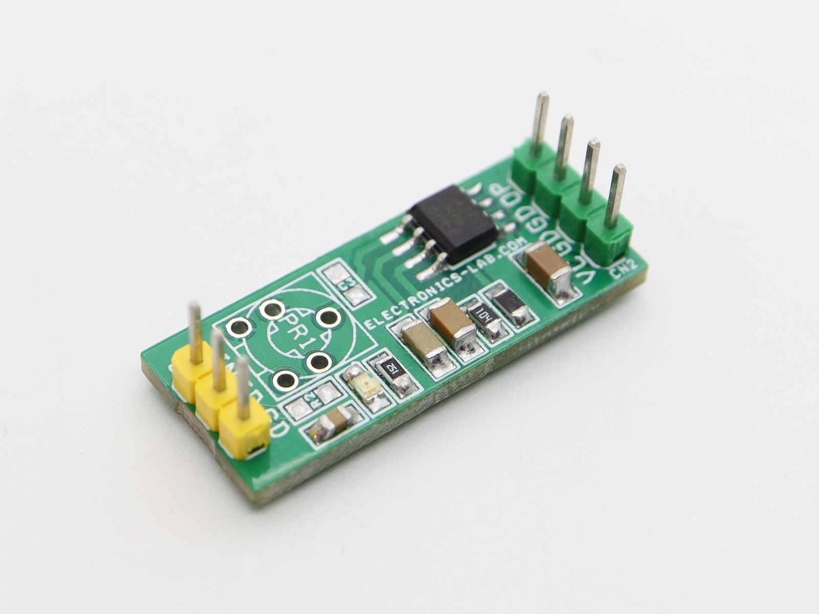
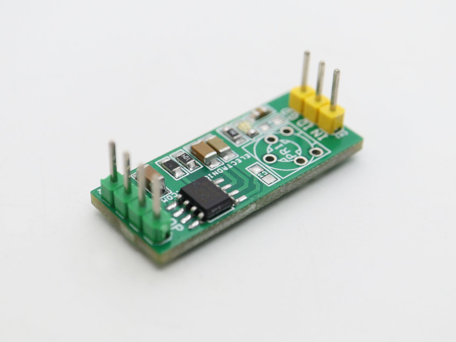
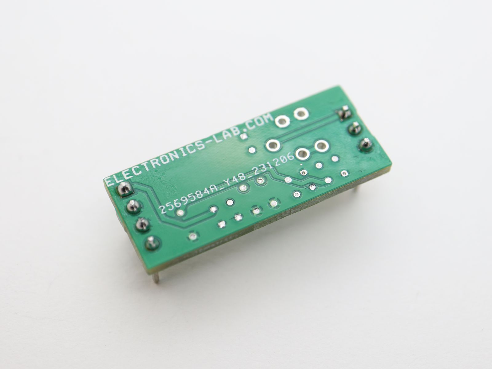
Photos
Hi.
I need something that measure up 120 KHz.
Does changing the chip to a LM2917 work?
You may do it using a frequency divider to divide 120KHz to the 1Khz this module accepts as maximum.