Arduino Communication with an Android App via Bluetooth
Introduction With the arrival of the IoT and the need for control, devices now need to do more than perform the basic functions for which they are built, they need to be capable of communicating with other devices like a mobile phone among others. There are different communication systems which can be adapted for communication between devices, they include systems like WiFi, RF, Bluetooth among several others.
Introduction
With the arrival of the IoT and the need for control, devices now need to do more than perform the basic functions for which they are built, they need to be capable of communicating with other devices like a mobile phone among others. There are different communication systems which can be adapted for communication between devices, they include systems like WiFi, RF, Bluetooth among several others. Our focus will be on communication over Bluetooth.
Today we will build an Arduino based project which communicates with an app running on a smartphone (Android) via Bluetooth.
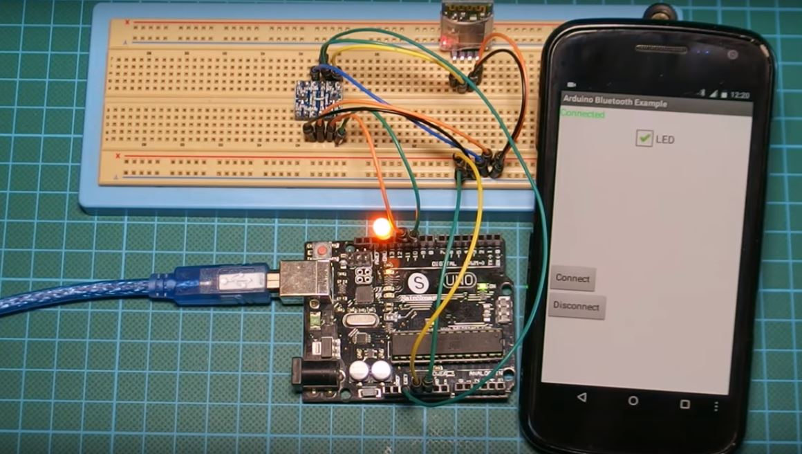
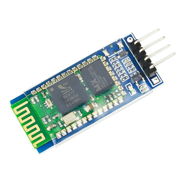
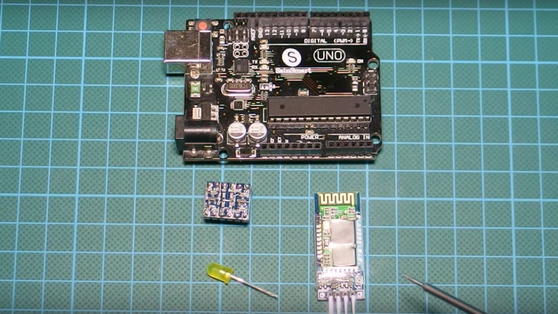
For simplicity, the goal of the project is to switch a LED connected to the Arduino using the mobile app. We will be using the HC06 Bluetooth module as the major ingredient in this tutorial.
The HC06 Bluetooth Module is a slave only version of the HC05 Bluetooth module. It has 4 pins and communicates with a microcontroller via serial interface.
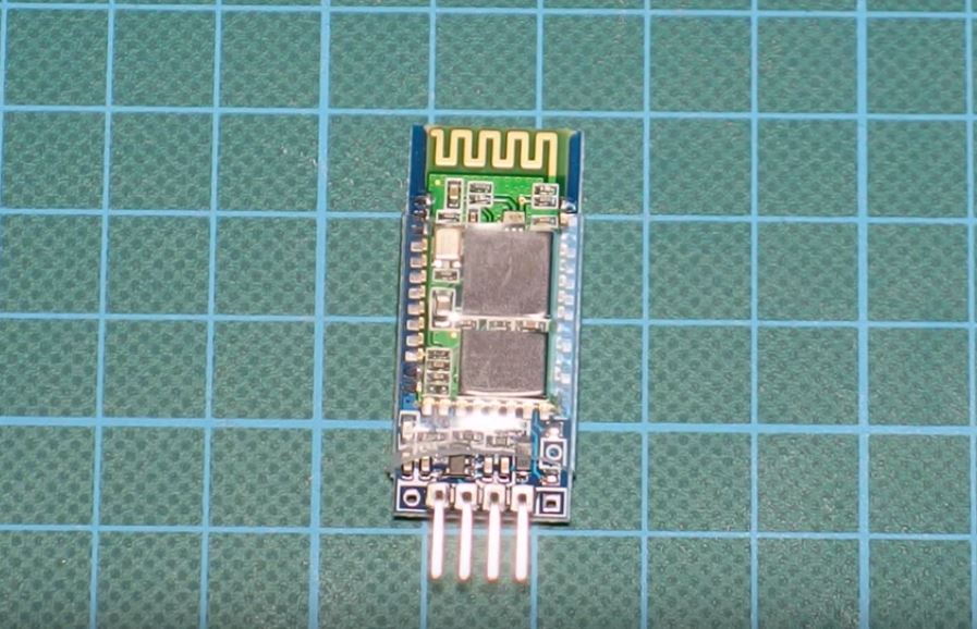
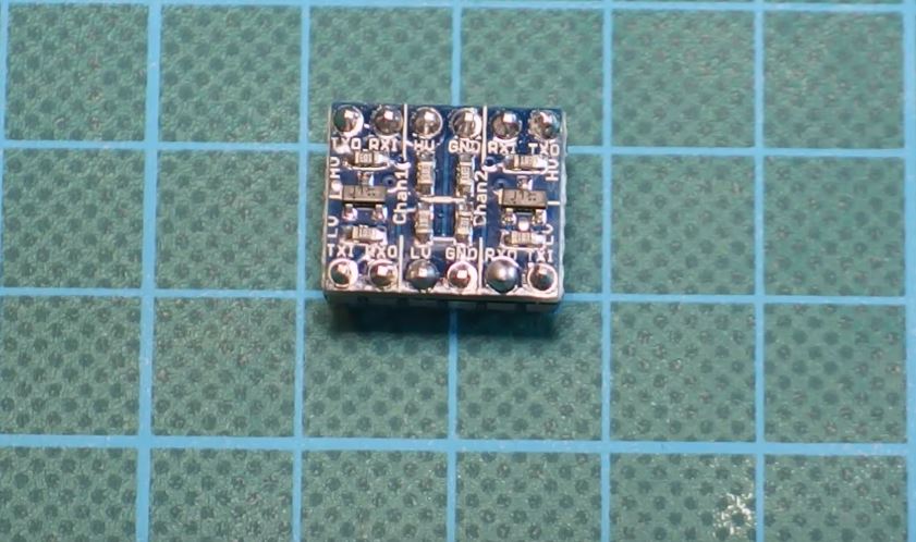
The HC06 Bluetooth module is a 3.3v logic level based device and thus if directly connected to the Arduino, will sometimes be unable to process the message received from the Arduino which is a 5v Level logic level device unless there exists some form of level shifting, although the Arduino can easily understand the data being sent from the Bluetooth module since it uses a higher logic level. The level shifting/conversion can be achieved either by use of a voltage divider or a level shifter module (like we did in this tutorial).
The shifter module (shown in the image below) helps with the easy transition from one voltage to the other. The level shifter has two sides, the high voltage side (marked HV) and the low voltage side (Marked LV). The shifter allows you to connect the desired low voltage output on the LV side and the high voltage line also to the HV. More details on connecting the level shifter are discussed in the schematics section.
Required Components
The following components are required for this tutorial;
As usual, the exact components used for this tutorial can be bought by following the link attached to each of them.
Schematics
Connect the components as shown in the schematics below.
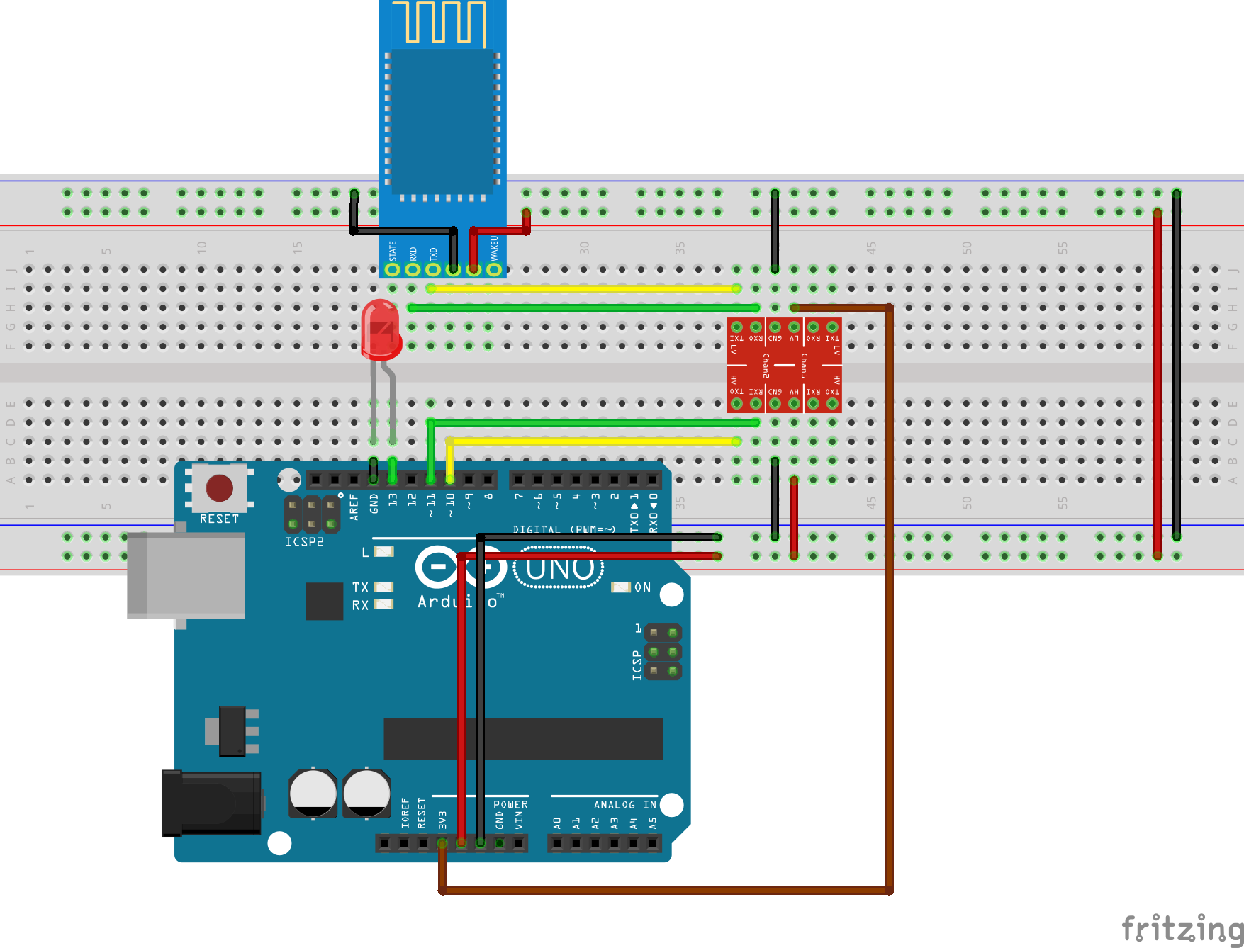
As earlier mentioned, the HC06 Bluetooth module is a 3.3v logic level device, to make it compatible with the logic level of the Arduino (which is 5v) we need to use a logic level shifter/converter as shown in the schematics above. To make the schematics a bit clearer, a pin map of the components and their connections is shown below.
Arduino – Logic converter
D10 - RX (HV Side)
D11 - Tx (HV Side)
Gnd - Gnd
3.3v - LV
5V - HV
HC06 – Logic Converter
Rx - Rx(LV side)
Tx - Tx(LV Side)
vcc - 5v (same as HV)
Gnd - Gnd
With the components connected and the connection verified, we are ready to build the Android app to be used for the actual control of the LED.
Android App
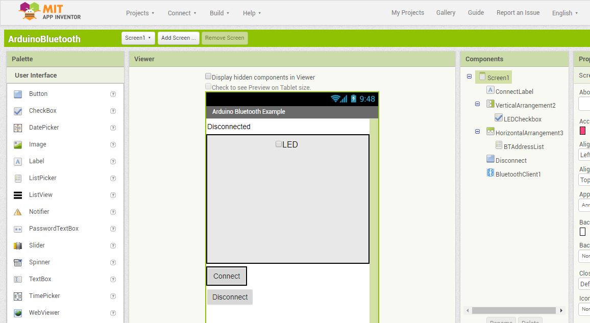
The app for this project was designed using the MIT app inventor for the sake of simplicity, but it can also be built using any other platform, used for the development of Android apps.
The MIT App Inventor is a scratch like mobile app development platform and its focus is around making programming easy for everyone, thus instead of writing codes, the app programming is done using drag and drop blocks just like the programming platform “Scratch”.
To build the app created for this project, create a new project and design the UI to look like the image below.
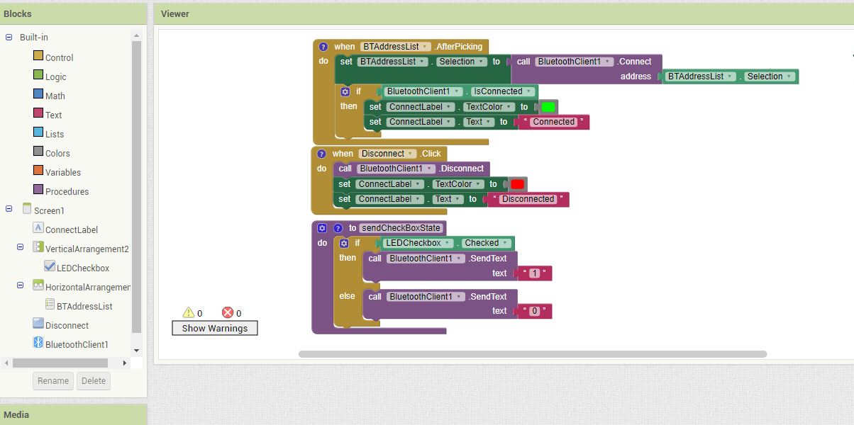
With the UI done, click on blocks and proceed to replicate the blocks below.
compile the app and save as an APK to your computer from which you can transfer to your phone for installation.
The .aia project raw file for the app is part of the files archived in the zip file located under the download section of this tutorial.
The .aia file can be imported into the MIT App inventor workspace and edited to suit your needs and desires.
The APK install ready file is also attached to the zip file, so you can install straight to your phone.
With the app ready, we can now proceed to write the Arduino code to control our device.
Code
The Arduino communicates with the Bluetooth module via serial communication and this makes it really easy to write the code. Since we decided to use software serial and not the Arduino’s hardware serial pins (D0 and D1), we will need the Arduino software serial library. This library gives us the freedom to choose any of the Arduino digital pins as our Rx and Tx pins. The hardware serial pins are the same pins used by the Arduino to communicate with the computer so connecting them to the Bluetooth will cause interference which could hinder the code upload process. Although the pins can be disconnected from the Bluetooth when the code is being uploaded and reconnected after the code has been uploaded but this is not always efficient.
The basic function of the code is to monitor the incoming serial data stream, if it receives a “1”, it turns the LED on and if it receives a “0” it turns the LED off.
To jump in, we will, as usual, give a breakdown of the code to explain each part before the full code is provided. The Arduino code is among the files archived in the zip file under the download section.
The first thing we do while writing the code, as usual, is to import the libraries we will be working with, which in this case is the software serial library.
    /////////////////////////////////////////////////////////////////
   //              Arduino Bluetooth Tutorial     v1.00           //
  //       Get the latest version of the code here:              //
 //         http://educ8s.tv/arduino-bluetooth-tutorial         //
/////////////////////////////////////////////////////////////////

#include <SoftwareSerial.h>
After importing the library, we then declare a variable to hold the characters received from the Bluetooth and the pin on the Arduino to which the LED is connected. We also initialize the Softwareserial library by indicating the pins that will serve as Rx and Tx.
char c;
int  LED = 13;

SoftwareSerial mySerial(10, 11);
Next, we move to the setup() section where we set the pinMode for the pin to which our LED is connected (output) and we start the serial communication with a baud rate of 9600 which is the baud rate at which most recent versions of the HC06 module communicate.
void setup()
{
  pinMode(LED, OUTPUT);
  mySerial.begin(9600);
}
Next, we move to the major part of the code; the void loop() function. The first thing we do is confirm the availability of data from the Bluetooth module, after which we read the data, and use an if statement to compare it to see if it is a 1 or 0. if the data is 1, we turn the LED high, but if its 0, we turn the LED off.
void loop()
{
  while (!mySerial.available());
  c = mySerial.read();
  if (c == '1')
  {
    digitalWrite(LED, HIGH);
  }
  if (c == '0')
  {
    digitalWrite(LED, LOW);
  }
}
The Complete code is available below.
    /////////////////////////////////////////////////////////////////
   //              Arduino Bluetooth Tutorial     v1.00           //
  //       Get the latest version of the code here:              //
 //         http://educ8s.tv/arduino-bluetooth-tutorial         //
/////////////////////////////////////////////////////////////////

#include <SoftwareSerial.h>

char c;
int  LED = 13;

SoftwareSerial mySerial(10, 11);

void setup()
{
  pinMode(LED, OUTPUT);
  mySerial.begin(9600);
}

void loop()
{
  while (!mySerial.available());
  c = mySerial.read();
  if (c == '1')
  {
    digitalWrite(LED, HIGH);
  }
  if (c == '0')
  {
    digitalWrite(LED, LOW);
  }
}
Demo
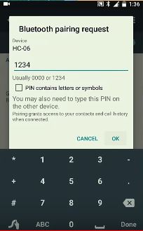
Connect, the Arduino to the computer and upload your code. You should see an LED on the Bluetooth begin to flash, this means it is ready to pair. Turn on your phone’s Bluetooth and you should see hc06 after scanning. connect to it and enter the passkey which is usually 1234.
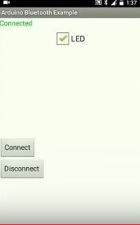
Proceed by launching the app, and click the connect button, it will show the mac address of your hc06. Connect to it and go back to the apps main screen.
After connecting, the app will show connected on the top left corner, you can then check or uncheck the checkbox to turn on or off the led respectively.
That’s it for today’s tutorial guys, If you have any question, suggestion or comment, kindly drop them under the comment section.
Till next time.
The video of this tutorial is available on youtube here.