Arduino RFID Reader using the ArduiTouch MKR Enclosure
RFID based projects are one of the most popular Arduino projects out there and we have also built a couple of them here too, but I recently came across an RFID access control project by hwhardsoft that was built using the ArduiTouch MKR enclosures. The ready-made nature of the enclosures and their existence for different kinds of boards caught my attention and I felt it might be of interest to most readers here too.
RFID based projects are one of the most popular Arduino projects out there and we have also built a couple of them here too, but I recently came across an RFID access control project by hwhardsoft that was built using the ArduiTouch MKR enclosures. The ready-made nature of the enclosures and their existence for different kinds of boards caught my attention and I felt it might be of interest to most readers here too. So for today’s project, we will build an RFID based Access Control system using the ArduiTouch MKR enclosure, an Arduino MKR WiFi 1010 and an InnovateKing-EU RFID reader.
The ArduiTouch series of enclosures come with a display already fitted on a PCB specifically designed for a specific family of maker board. The best way to describe them will be “evaluation boards with screens and enclosures for maker boards”. The ArduiTouch MKR enclosure to be used today, was designed for the Arduino MKR family of boards and it comes with; an 120 x 80 x 33 mm enclosure for top wall mounting, a 2.4-inch resistive touch TFT, an integrated voltage regulator, an integrated piezo beeper, breadboard area for easy mounting of components, and a slot for an MKR shield.
All of the above features make it easy to create a very nice looking RFID reader, with TFT output for wall/door mounting with an Arduino MKR of your choice. The Arduino MKR of choice selected for this tutorial is the Arduino MKR WiFi 1010, and the RFID module selected is the InnovateKing-EU RFID Reader.
At the end of today’s tutorial, you would know not only how to build a fancy RFID reader but also the intricacies of working with an ArduiTouch MKR Enclosure and using the InnovateKing-EU RFID Reader.
Required Components
The following components are required to build this project:
All of these components can be bought via the attached links, and you could choose to go with other versions/types of components like a different Arduino MKR board or a different RFID Reader. Just ensure you take note of the changes that might be introduced into other parts of the project (like schematics and code) as a result of that.
Schematics
As mentioned earlier, today’s project is centered around the ArduiTouch MKR evaluation board. What this means is that we do not need to worry about arranging the components on a breadboard or designing a PCB to make things compact. All we need to do is to connect the components to the right pins on the ArduiTouch MKR PCB and off we go. The display and Arduino MKR WiFi 1010 already have their pins mapped out on the board as such we only need to plug them in, but the InnovateKing-EU RFID Reader needs to be connected to specific pins on the board. The schematics showing how it is connected is provided in the image below;
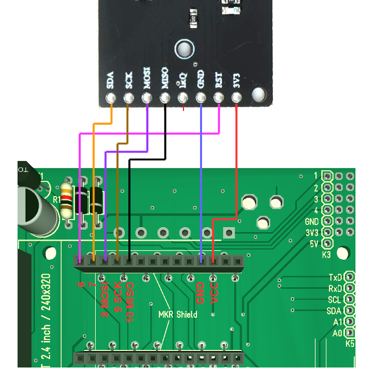
The InnovateKing-EU RFID reader is connected to the SPI pins of the MKR. A pin to pin map describing the connection is provided below:
MKR – InnovateKing-EU Rfid Reader
GND - GND
VCC - 3.3V
D6 - RST
D7(CS) - SDA
D9(SCK) - SCK
D8(MOSI) - MOSI
D10(MISO) - MISO
You can connect the RFID Reader using jumper cables such that, the complete setup with all the components plugged in, looks like the image below.
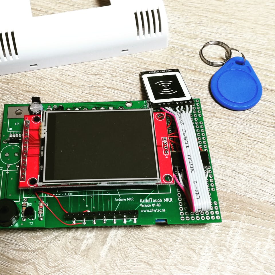
With this done, we can proceed to write the code for the project.
Code
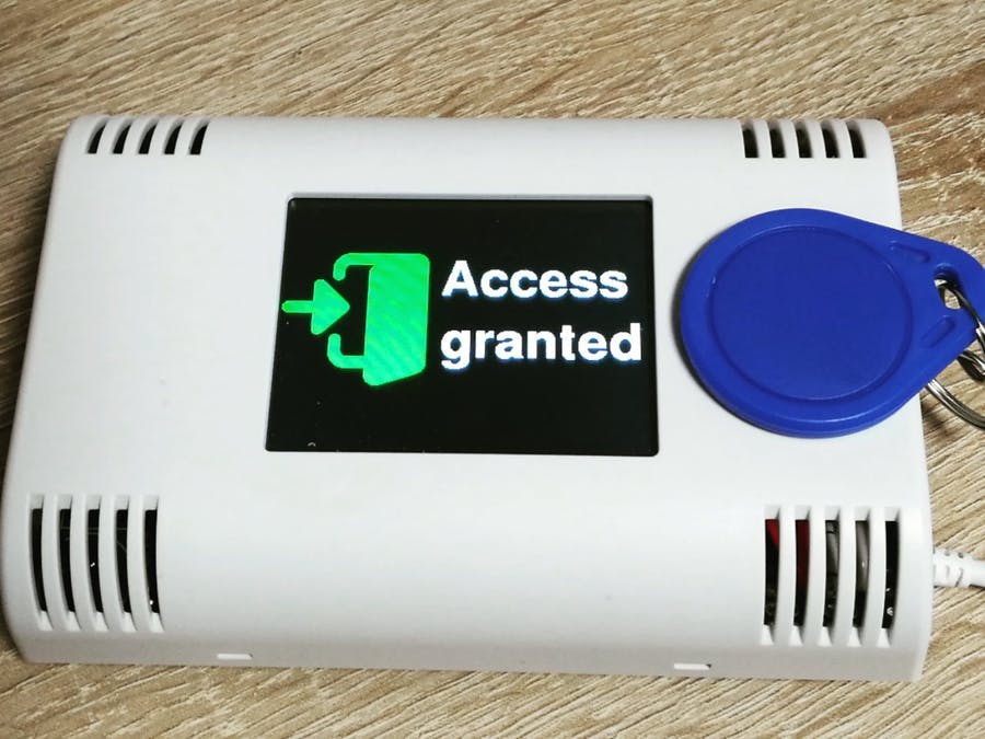
The code for this project is quite straightforward. We will read the UID of the RFID tags and if they match pre-stored UID values, we will take certain actions like triggering a relay and displaying Access granted or Denied along with the UID of the tag. The relay triggering action could be matched to so many things like a door lock being opened among other things.
To reduce the amount of work we have to do with writing the code, we will be using three major libraries including; the Adafruit GFX Library, the Adafruit ILI9341 Library, and the MFRC522 Library. The MFRC522 library facilitates interaction with the RFID reader while the ILI9341 and GFX libraries facilitate the display of text and graphics on the TFT. All three libraries can be downloaded from the links attached to each of them or installed via the Arduino Library Manager.
With the libraries installed, we can then proceed to write the code for the project. As usual, I will do a quick breakdown of the code, explaining key concepts.
We start the code as usual by including the libraries and header files we will be working with. Asides the libraries already mentioned above, we will be using some fonts and usergraphics. .h header file which contains the char representation of the custom images that will be displayed on the TFT. You can check out this tutorial on displaying custom graphics on LCD display to learn how the .h file was created.
Next, we declare the pins of the Arduino MKR to which the pins of the TFT LCD, along with other components like the relay and RFID readers, are connected.
/*__Pin definitions for the Arduino MKR__*/
#define TFT_CS   A3
#define TFT_DC   0
#define TFT_MOSI 8
#define TFT_CLK  9
#define TFT_MISO 10
#define TFT_LED  A2


#define HAVE_TOUCHPAD
#define TOUCH_CS A4
#define TOUCH_IRQ 1

#define BEEPER 2
#define RELAY A0   // optional relay output

// RFID
#define RST_PIN   6     // SPI Reset Pin
#define SS_PIN    7    // SPI Slave Select Pin

/*_______End of definitions______*/
Next, the calibration value for the screen is entered, this can be obtained by running the calibration sketch in the Adafruit ILI9341 library.
/*____Calibrate Touchscreen_____*/
#define MINPRESSURE 10      // minimum required force for touch event
#define TS_MINX 370
#define TS_MINY 470
#define TS_MAXX 3700
#define TS_MAXY 3600
/*______End of Calibration______*/
Next, we need to specify the UID’s to be allowed access. Normally this should have been done using an “enroll” process but to save time, you can get the UID of each card by uploading the code to the board and trying out each of the tags. Their UID will be displayed at the bottom of the result and you can then enter that UID into the sketch and re-upload the code. This is definitely not elegant and should be an improvement to the project.
/*___Keylock spezific definitions___*/
byte blue_uid[] = {0x09, 0x8D, 0x9D, 0xA3};
#define relay_on_time 30 // will set the relay on for 3s
/*___End of Keylock spezific definitions___*/
Next, we create an instance of the libraries and create a few more variables to hold different parameters during the code execution.
Adafruit_ILI9341 tft = Adafruit_ILI9341(TFT_CS, TFT_DC);
XPT2046_Touchscreen touch(TOUCH_CS);
MFRC522 mfrc522(SS_PIN, RST_PIN);


int X,Y;
long Num1,Num2,Number;
char action;
boolean result = false;
bool Touch_pressed = false;
TS_Point p;
int RELAYTMR = 0; // Timer for relay control
int blue_check = false;
int red_check = false;
String s1;
With this done, we move to the void setup() function. We start the function by initializing the serial monitor and setting the pin mode of the Relay pin.
void setup() {
  Serial.begin(115200); //Use serial monitor for debugging

  pinMode(TFT_LED, OUTPUT); // define as output for backlight control
  pinMode(RELAY, OUTPUT);   // define as output for optional relay
  digitalWrite(RELAY, LOW); // LOW to turn relay off
Next, we initialize the TFT, setting it to a preferred orientation using the tft.setRotation function.
Serial.println("Init TFT and Touch...");
  tft.begin();
  touch.begin();
  tft.setRotation(3);
  Serial.print("tftx ="); Serial.print(tft.width()); Serial.print(" tfty ="); Serial.println(tft.height());
Next, we set the background of the display to black and turn of the display’s backlight.
tft.fillScreen(ILI9341_BLACK);
digitalWrite(TFT_LED, HIGH);    // HIGH to turn backlight off - will hide the display during drawing
The function ends with the initialization of the RFID reader.
 Serial.println("Init RFC522 module....");
  mfrc522.PCD_Init();  // Init MFRC522 module
}
Next is the void loop function.
The void loop function is quite straight forward. We start by checking if the reader detects a tag. if this is so, the UID of the tag is read and it is checked with the pre-stored UID (blue_UID).
void loop() {
  // only after successful transponder detection the reader will read the UID
  // PICC = proximity integrated circuit card = wireless chip card
  if (mfrc522.PICC_IsNewCardPresent() && mfrc522.PICC_ReadCardSerial() ) {
    Serial.print("Gelesene UID:");
    s1 = "";
    for (byte i = 0; i < mfrc522uid.size; i++) {
      // Abstand zwischen HEX-Zahlen und fhrende Null bei Byte < 16
      s1 = s1 + (mfrc522.uid.uidByte[i] < 0x10 ? " 0" : " ");
      s1 = s1 + String(mfrc522.uid.uidByte[i], HEX);
    }
    s1.toUpperCase();
    Serial.println(s1);


    // check current UID with blue_uid
    blue_check = true;
    for (int j=0; j<4; j++) {
      if (mfrc522.uid.uidByte[j] != blue_uid[j]) {
        blue_check = false;
      }
    }
If the check returns a true value (indicating a match), the granted screen (or any other action you desire for a positive match) is displayed via the function call, but if a false value is returned, the denied screen is displayed along with the tags UID. The loop is repeated and the process goes on and on.
if (blue_check)
  {
    Granted_Screen();
  } else {
     Denied_Screen(s1);
  }
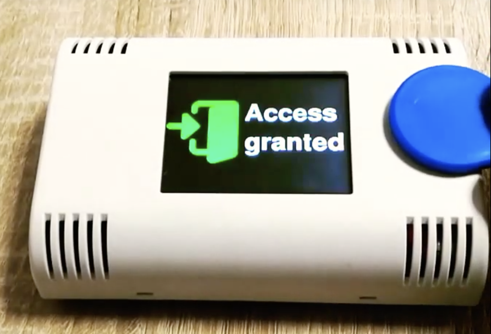
The Granted_Screen() function fetches a matching icon from the usergraphics.h file and displays it using the drawBitmap() function, while also displaying matching text and triggering the relay.
void Granted_Screen(){

  // show symbol
  tft.drawBitmap(0,50, access_granted,128,128,ILI9341_GREEN);
  tft.setTextSize(0);
  tft.setTextColor(ILI9341_WHITE);
  tft.setFont(&FreeSansBold24pt7b);
  tft.setCursor(140, 90 );
  tft.println("Access");
  tft.setCursor(140, 150);
  tft.println("granted");
  digitalWrite(TFT_LED, LOW);    // LOW to turn backlight on
  digitalWrite(RELAY, HIGH);     // HIGH to turn relay on
  tone(BEEPER,1000,800);
  delay(1200);
  digitalWrite(TFT_LED, HIGH);   // HIGH to turn backlight off
  tft.fillRect(0, 0, 320, 240, ILI9341_BLACK); // clear screen
  digitalWrite(RELAY, LOW); // LOW to turn relay off
}
The same holds for the Denied_Screen() function. A matching icon is fetched and displayed along with text and that illustrates the Icon.
void Denied_Screen(String sUID) {

  // show symbol
  tft.drawBitmap(0,40, access_denied,128,128,ILI9341_RED);
  // show result text
  tft.setTextSize(0);
  tft.setTextColor(ILI9341_WHITE);
  tft.setFont(&FreeSansBold24pt7b);
  tft.setCursor(140, 90 );
  tft.println("Access");
  tft.setCursor(140, 150);
  tft.println("denied");
  tft.setFont(&FreeSans9pt7b);
  // show UID
  tft.setCursor(90, 200);
  tft.println("UID:");
  tft.setCursor(140, 200);
  tft.println(sUID);
  digitalWrite(TFT_LED, LOW); // LOW to turn backlight on
  for (int i=0;i< 3;i++) {
          tone(BEEPER,4000);
          delay(100);
          noTone(BEEPER);
          delay(50);
  }
  delay(1500);
  digitalWrite(TFT_LED, HIGH);   // HIGH to turn backlight off
  tft.fillRect(0, 0, 320, 240, ILI9341_BLACK);  // clear screen
}
The complete code for the project is provided below and also attached under the download section.
/*______Import Libraries_______*/
#include <Arduino.h>
#include <SPI.h>
#include <MFRC522.h>
#include "Adafruit_GFX.h"
#include "Adafruit_ILI9341.h"
#include <XPT2046_Touchscreen.h>
#include <Fonts/FreeSans9pt7b.h>
#include <Fonts/FreeSansBold9pt7b.h>
#include <Fonts/FreeSansBold24pt7b.h>
#include "usergraphics.h"
/*______End of Libraries_______*/


/*__Pin definitions for the Arduino MKR__*/
#define TFT_CS   A3
#define TFT_DC   0
#define TFT_MOSI 8
#define TFT_CLK  9
#define TFT_MISO 10
#define TFT_LED  A2


#define HAVE_TOUCHPAD
#define TOUCH_CS A4
#define TOUCH_IRQ 1

#define BEEPER 2
#define RELAY A0   // optional relay output

// RFID
#define RST_PIN   6     // SPI Reset Pin
#define SS_PIN    7    // SPI Slave Select Pin

/*_______End of definitions______*/


/*____Calibrate Touchscreen_____*/
#define MINPRESSURE 10      // minimum required force for touch event
#define TS_MINX 370
#define TS_MINY 470
#define TS_MAXX 3700
#define TS_MAXY 3600
/*______End of Calibration______*/


/*___Keylock spezific definitions___*/
byte blue_uid[] = {0x09, 0x8D, 0x9D, 0xA3};
#define relay_on_time 30 // will set the relay on for 3s
/*___End of Keylock spezific definitions___*/


Adafruit_ILI9341 tft = Adafruit_ILI9341(TFT_CS, TFT_DC);
XPT2046_Touchscreen touch(TOUCH_CS);
MFRC522 mfrc522(SS_PIN, RST_PIN);


int X,Y;
long Num1,Num2,Number;
char action;
boolean result = false;
bool Touch_pressed = false;
TS_Point p;
int RELAYTMR = 0; // Timer for relay control
int blue_check = false;
int red_check = false;
String s1;


void setup() {
  Serial.begin(115200); //Use serial monitor for debugging

  pinMode(TFT_LED, OUTPUT); // define as output for backlight control
  pinMode(RELAY, OUTPUT);   // define as output for optional relay
  digitalWrite(RELAY, LOW); // LOW to turn relay off

  Serial.println("Init TFT and Touch...");
  tft.begin();
  touch.begin();
  tft.setRotation(3);
  Serial.print("tftx ="); Serial.print(tft.width()); Serial.print(" tfty ="); Serial.println(tft.height());

  tft.fillScreen(ILI9341_BLACK);
  digitalWrite(TFT_LED, HIGH);    // HIGH to turn backlight off - will hide the display during drawing
  Serial.println("Init RFC522 module....");
  mfrc522.PCD_Init();  // Init MFRC522 module
}


void loop() {
  // only after successful transponder detection the reader will read the UID
  // PICC = proximity integrated circuit card = wireless chip card
  if (mfrc522.PICC_IsNewCardPresent() && mfrc522.PICC_ReadCardSerial() ) {
    Serial.print("Gelesene UID:");
    s1 = "";
    for (byte i = 0; i < mfrc522.uid.size; i++) {
      // Abstand zwischen HEX-Zahlen und fhrende Null bei Byte < 16
      s1 = s1 + (mfrc522.uid.uidByte[i] < 0x10 ? " 0" : " ");
      s1 = s1 + String(mfrc522.uid.uidByte[i], HEX);
    }
    s1.toUpperCase();
    Serial.println(s1);


    // check current UID with blue_uid
    blue_check = true;
    for (int j=0; j<4; j++) {
      if (mfrc522.uid.uidByte[j] != blue_uid[j]) {
        blue_check = false;
      }
    }

    if (blue_check)
    {
      Granted_Screen();
    } else {
       Denied_Screen(s1);
    }
  }
}

/********************************************************************//**
 * @brief     detects a touch event and converts touch data
 * @param[in] None
 * @return    boolean (true = touch pressed, false = touch unpressed)
 *********************************************************************/
bool Touch_Event() {
  p = touch.getPoint();
  delay(1);
  #ifdef touch_yellow_header
    p.x = map(p.x, TS_MINX, TS_MAXX, 320, 0); // yellow header
  #else
    p.x = map(p.x, TS_MINX, TS_MAXX, 0, 320); // black header
  #endif
  p.y = map(p.y, TS_MINY, TS_MAXY, 0, 240);
  if (p.z > MINPRESSURE) return true;
  return false;
}


/********************************************************************//**
 * @brief     shows the intro screen in setup procedure
 * @param[in] None
 * @return    None
 *********************************************************************/
void IntroScreen()
{
  //Draw the Result Box
  tft.fillRect(0, 0, 240, 320, ILI9341_WHITE);
  tft.drawRGBBitmap(20,80, Zihatec_Logo,200,60);
  tft.setTextSize(0);
  tft.setTextColor(ILI9341_BLACK);
  tft.setFont(&FreeSansBold9pt7b);

  tft.setCursor(42, 190);
  tft.println("ArduiTouch MKR");

  tft.setCursor(55, 215);
  tft.println("RFID example");
}


/********************************************************************//**
 * @brief     shows the granted screen on tft & switch optional relay
 * @param[in] None
 * @return    None
 *********************************************************************/
void Granted_Screen(){

  // show symbol
  tft.drawBitmap(0,50, access_granted,128,128,ILI9341_GREEN);
  tft.setTextSize(0);
  tft.setTextColor(ILI9341_WHITE);
  tft.setFont(&FreeSansBold24pt7b);
  tft.setCursor(140, 90 );
  tft.println("Access");
  tft.setCursor(140, 150);
  tft.println("granted");
  digitalWrite(TFT_LED, LOW);    // LOW to turn backlight on
  digitalWrite(RELAY, HIGH);     // HIGH to turn relay on
  tone(BEEPER,1000,800);
  delay(1200);
  digitalWrite(TFT_LED, HIGH);   // HIGH to turn backlight off
  tft.fillRect(0, 0, 320, 240, ILI9341_BLACK); // clear screen
  digitalWrite(RELAY, LOW); // LOW to turn relay off
}


/********************************************************************//**
 * @brief     shows the access denied screen on tft
 * @param[in] None
 * @return    None
 *********************************************************************/
void Denied_Screen(String sUID) {

  // show symbol
  tft.drawBitmap(0,40, access_denied,128,128,ILI9341_RED);
  // show result text
  tft.setTextSize(0);
  tft.setTextColor(ILI9341_WHITE);
  tft.setFont(&FreeSansBold24pt7b);
  tft.setCursor(140, 90 );
  tft.println("Access");
  tft.setCursor(140, 150);
  tft.println("denied");
  tft.setFont(&FreeSans9pt7b);
  // show UID
  tft.setCursor(90, 200);
  tft.println("UID:");
  tft.setCursor(140, 200);
  tft.println(sUID);
  digitalWrite(TFT_LED, LOW); // LOW to turn backlight on
  for (int i=0;i< 3;i++) {
          tone(BEEPER,4000);
          delay(100);
          noTone(BEEPER);
          delay(50);
  }
  delay(1500);
  digitalWrite(TFT_LED, HIGH);   // HIGH to turn backlight off
  tft.fillRect(0, 0, 320, 240, ILI9341_BLACK);  // clear screen
}


/********************************************************************//**
 * @brief     plays ack tone (beep) after button pressing
 * @param[in] None
 * @return    None
 *********************************************************************/
void Button_ACK_Tone(){
  tone(BEEPER,4000,100);
}
Demo
With the code complete, connect the MKR board to your computer and upload the code. To pre-store a UID, place it on the reader and write down the displayed ID on the Access Denied page as shown below.
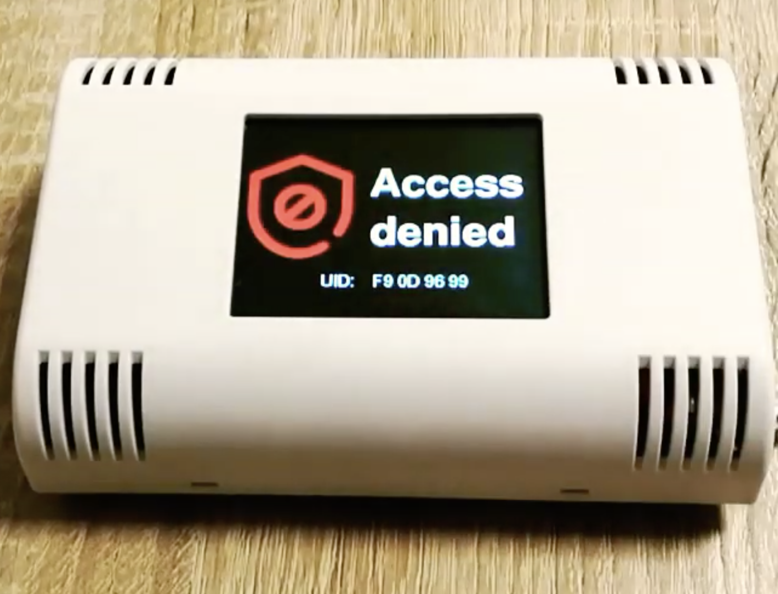
Assign this value to the blue_uid variable at the top of the code and re-upload the code to the MKR. The card with the Blue UID should now get an “Access Granted” response while others will get an “Access denied“response.
That’s it for this project, thanks for reading. Yes definitely, the first thing you should do as an upgrade to the project is to create an enroll sketch to allow you add multiple “blue_uids” and then maybe connect the project to the internet to get live updates on who just accessed the door. The project is quite fun and it demonstrates the ease with which you can build really cool looking projects using the ArduiTouch Enclosures.
Feel free to reach me via the comment section if you have any questions as regards replicating the project.