DC Motor Driver using L293D
- Ricardo Márquez
- ricardo-m-m@hotmail.com
- 49.735 Views
- medium
- Non tested
This project is a DC motor driver, suitable for motors of low or medium power. Allows controlling up to 6 motors or 3 motors if you want to control the rotation of the motors.
Description
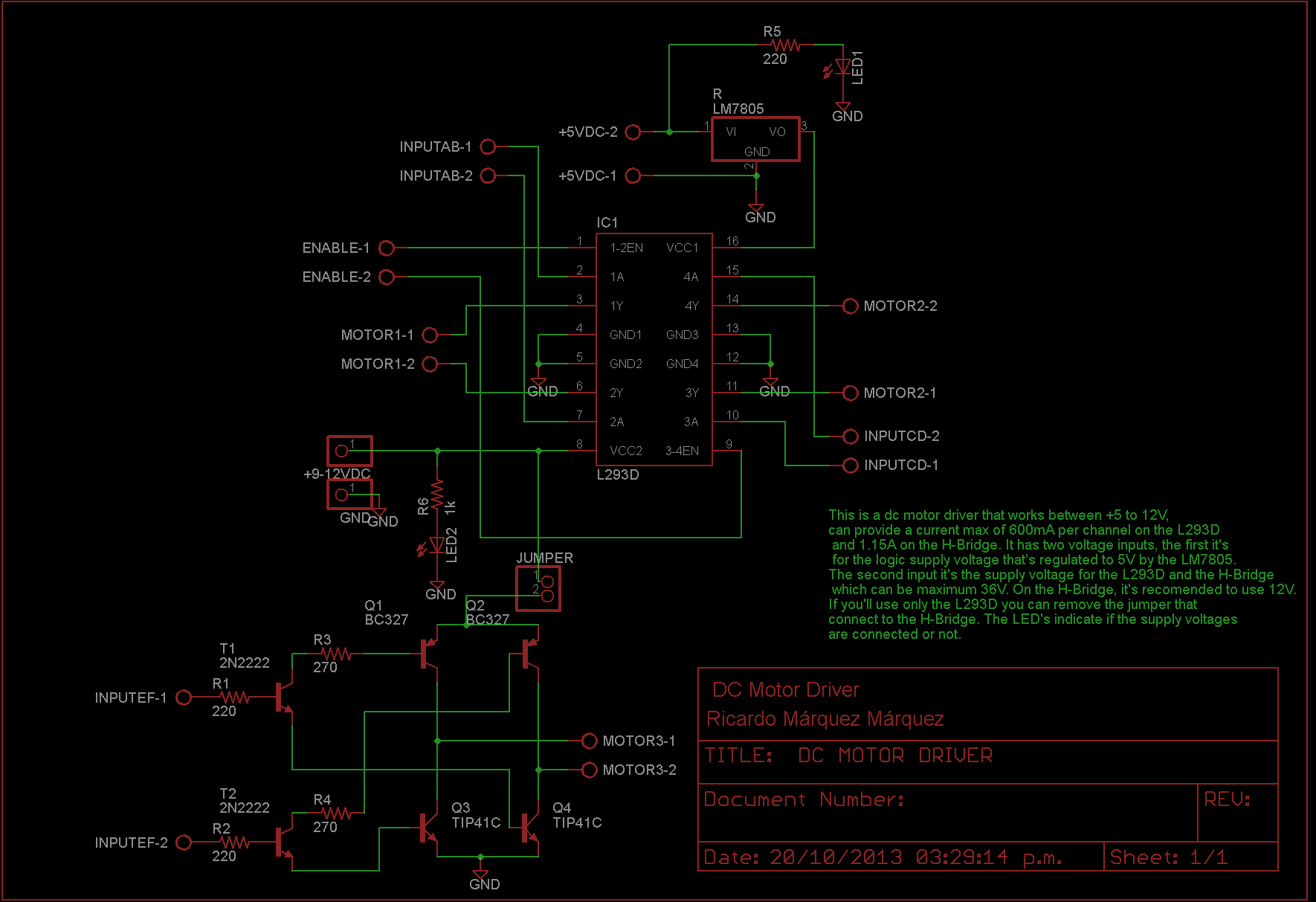
The controller is build around the IC L293D that can provide 600mA per channel, and a H-Bridge designed with transistors NPN and PNP transistors, than can provide 1.15A per channel.
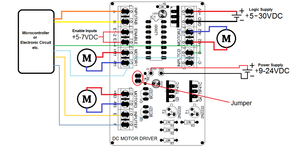
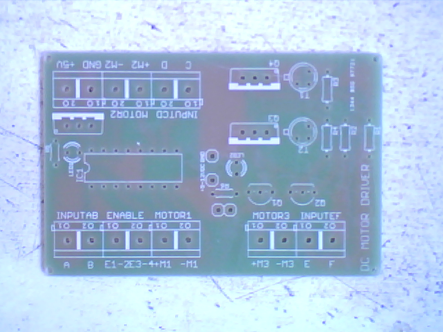
The controller has the following connections:
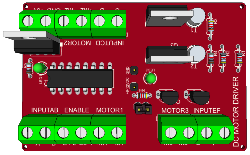
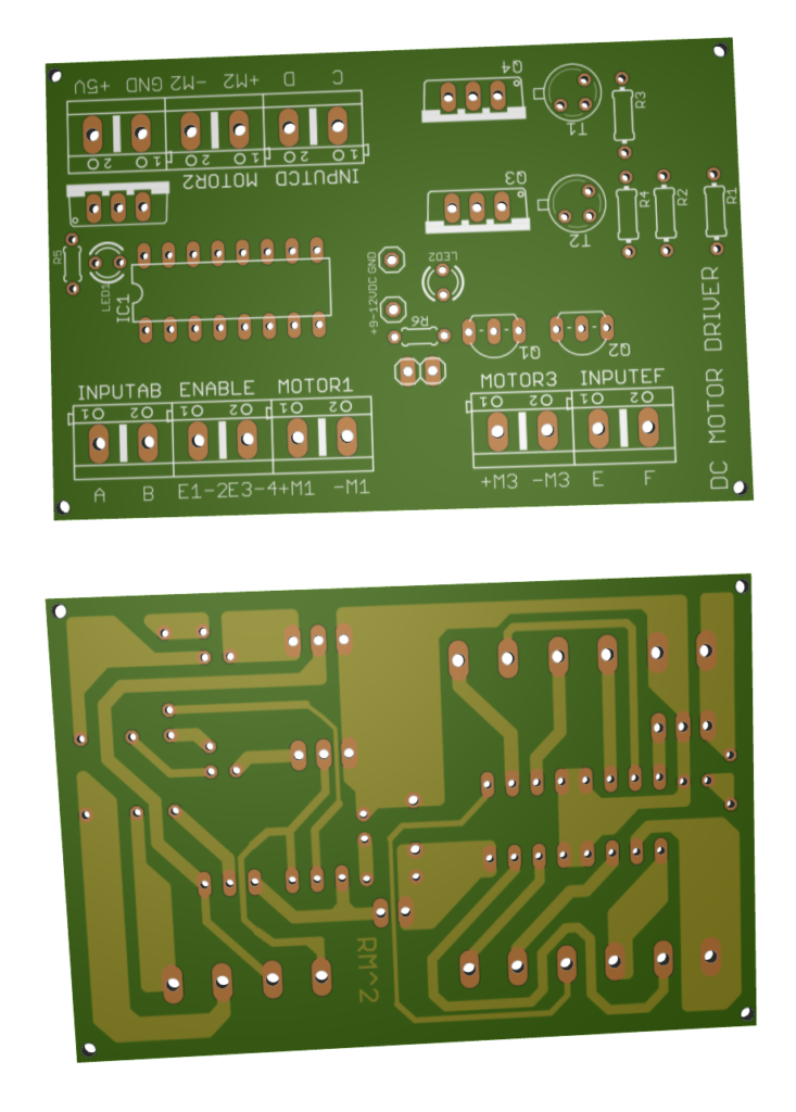
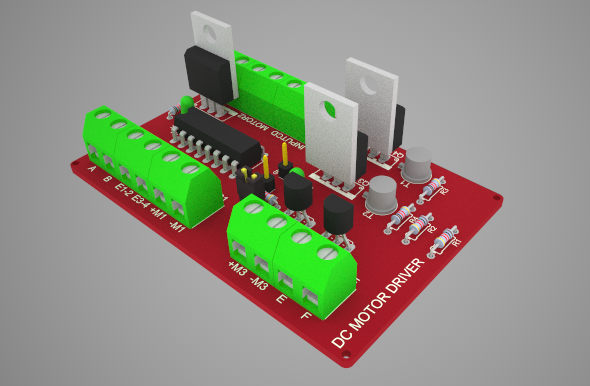
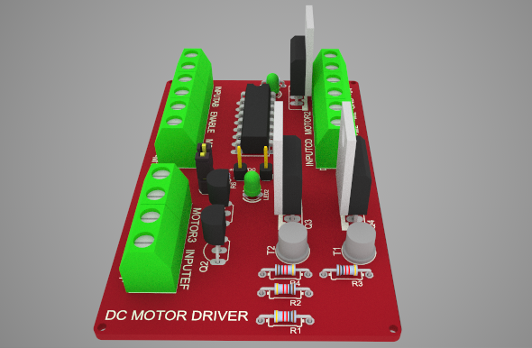
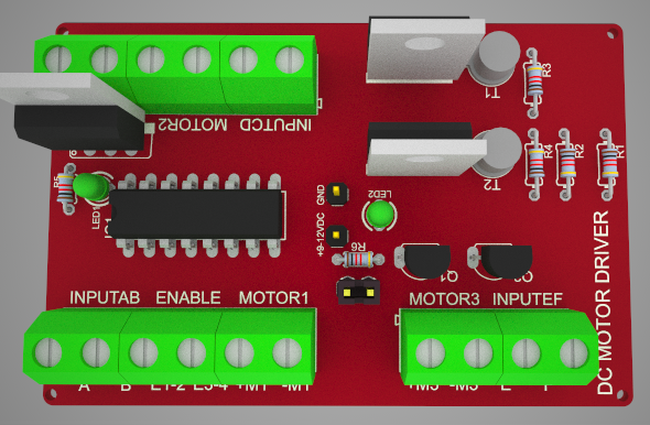
- INPUTS (A, B, C, D ,E, F). These are receiving the analog or digital signals that can be sent for example, from a microcontroller.
- ENABLE (E1-2, E3-4). These activate the inputs from the L293D. The supply voltage can’t be higher than 7V.
- OUTPUTS (+M1, -M1, +M2, -M2, +M3, -M3). Here is where the motors should be connected.
- +9-12V. Here’s where is connected a supply voltage that will give power to the motors. This input, gives voltage in the L293D and the H-Bridge, the supplied voltage have to be 36V max, but for the H-Bridge it’s recommendable to use 24V max. (In case you want to use only the L293D, you can remove the jumper).
- +5V. This input receive the logic supply voltage for the L293D. You can connect a supply voltage higher than 5V because this input it’s connected to a voltage regulator (LM7805), but you not must to exceed 30V.
Schematic
Connections
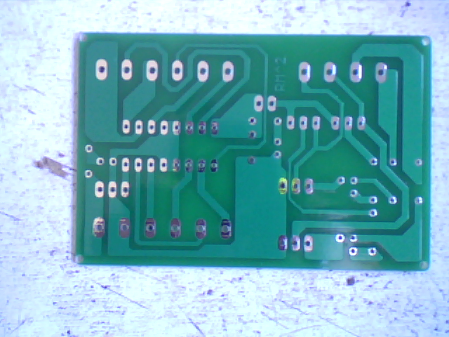
PCB
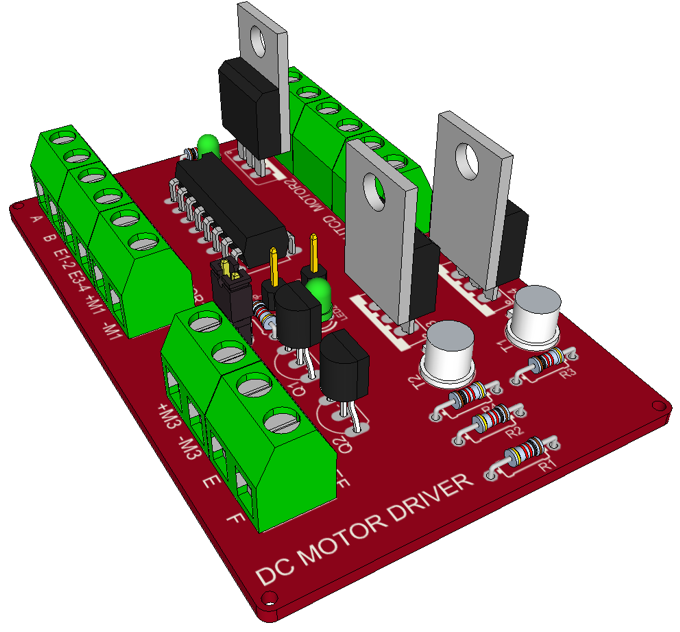
3D PCB



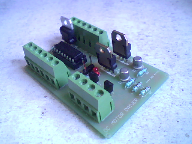
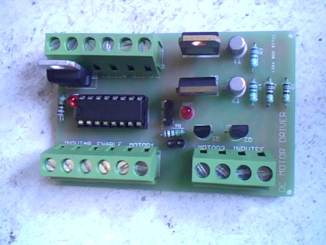


I have a circuit of your products which has a L293D, 2 resistors, 2 led’s,2 motor slots(motor1 & motor2), 3 pins {GNG},and some more pins will please tell me what is it ?and how to use it ? Thank you
L293D is a dual H-bridge motor driver integrated circuit (IC). It can control two DC motors simultaneously. The motor operation of the two motors can be controlled by input logic at pins 2 & 7 and 10 & 15. Input logic 00 or 11 will stop the corresponding motor. Logic 01 and 10 will rotate it in clockwise and anticlockwise directions, respectively.
How to give control signal to L293D? can it be given through Arduino ? If so how to program it? Kindly give a resource.
Check this https://learn.adafruit.com/adafruit-arduino-lesson-15-dc-motor-reversing/lm293d on how to control L293D with arduino board. Example code is provided.
Hye, I would like to ask can the driver control 3 motors simultaneously? since there are 3 motor output shown in the diagram.
Yes, it can control 3 motors simultaneously.
Hello, can it use CNC driver? https://www.youtube.com/watch?v=OzF3m-P1nFM
This is used to control DC motors only.
Can this control 4 motors?
This circuit can only control 3 DC motors.
Hello, i must say that’s a quite great board. If you still up answers to questions, i got some because i’m looking to redraw the schematic and try to add another l293d to control 4 motors (2 motors both on each IC chips), but i’m not that bright to understand how to rewire the resistor and the capacitor. Do you need to draw another one of each, or just try to wire it?
You could try to create 2 identical boards sharing the same power source and logic power, as long as it can provide enough power for the boards and motor. Then you can use 4 signals to control the motors.
I just finished my board! If there is any way i can share the picture with you i would be happy to do so?
You can share it in the community. Feel free to register and post your progress.