Position and Speed Controller for DC Motor with Incremental Encoder
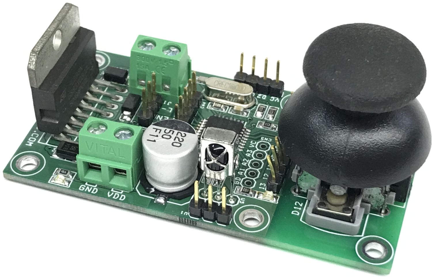
This project consists of Arduino Arduino-compatible microcontroller ATmega328, an L298 Motor driver, a Joystick, a programming connector, an Infrared sensor, and various analog and digital I/O pins. The project is Arduino compatible and can be programmed using Arduino IDE and many motor-related projects can be developed using this hardware.
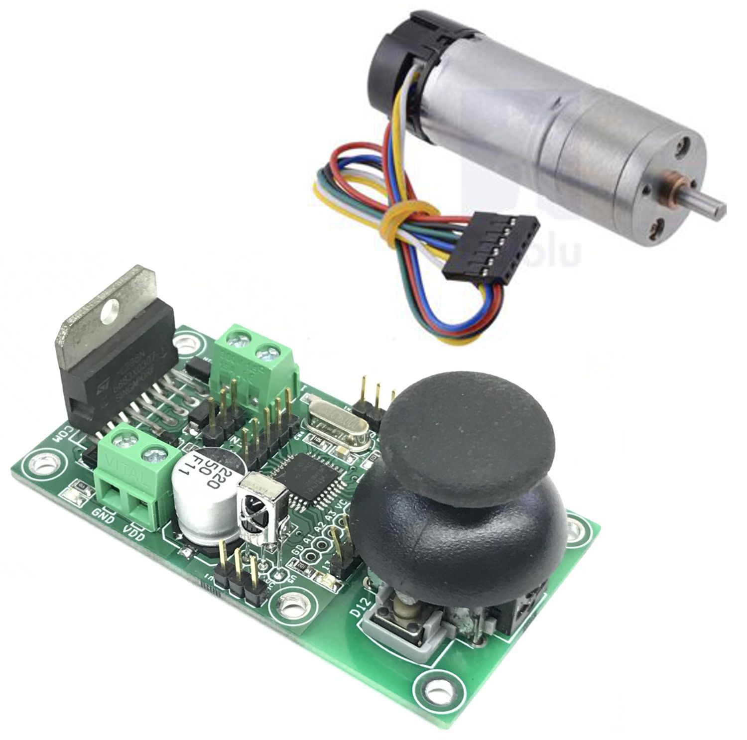
This project consists of Arduino Arduino-compatible microcontroller ATmega328, an L298 Motor driver, a Joystick, a programming connector, an Infrared sensor, and various analog and digital I/O pins. The project is Arduino compatible and can be programmed using Arduino IDE and many motor-related projects can be developed using this hardware. L298 has two H-bridges but here in this project the two H-bridges are configured/connected in parallel to provide more power to the motor, D9, and D10 are connected to the Input of L298 and these two pins can be used to control the direction of the motor or direction and speed. D5 is connected to the Enable pin of L298 and can be used for PWM input for speed control or to enable the L298. Connector CN1 is provided to connect the incremental encoder to Channel A and Channel B and Arduino and D2, D3 interrupt pins of the Arduino, these two pins have also pullups. The operating power supply for the motor is 7V to 46V DC, logic supply is 5VDC. If the motor voltage is below 18V, the project can work with a single supply, in this case, install the LM7805 regulator provided under the PCB.
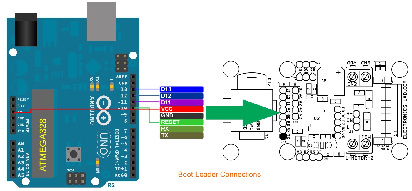
Arduino code is available to test the project, and you can edit the appropriate PID values to tune the motor. Check the link below for more information about boot-loader and Arduino programming, also refer to the connection diagram for the same.
Arduino Compatible Motor Driver Key Features
- Atmega328 Arduino Compatible Microcontroller
- L298 H Bridge Bidirectional DC Motor Driver
- Joystick + Switch Joystick Connected to A1, Switch Connected to D12 + GND
- CN3 Arduino Programming/Bootloader Connector
- CN5 Analog I/O, A1, A2, A3 (For External Sensor or I/))
- CN4 Digital I/O D6, D7, D8 (For I/O)
- CN1 Digital Pin D2, D3 (For Incremental Encode A and B Channel) With Pull-ups (Interrupt Pins)
- Jumper J1 Enable Control for L298, Optional Jumper Do Note Populate
- U1 External Potentiometer (VCC, Analo A0, GND)
- LM78M05 5V Regulator Optional Only Use when Motor Power Supply 18V Maximum
- D1 Logic Power LED
- D4 Motor Power LED
Applications
- PID Closed-Loop DC Motor with Incremental Encoder Feedback for Position Control
- PID Closed-Loop DC Motor with Potentiometer Feedback Potion Control
- DC Motor Speed Controller Open Loop
- DC Motor Speed Controller Closed Loop (Velocity Control)
- DC Motor Speed Control Using IR Remote
- DC Motor Speed and Direction Control Using Joystick Open Loop or Closed Loop
- DC Motor Speed and Direction Control Using External Potentiometer Open Loop or Closed Loop
Features
- Power Supply Motor 7V to 46V DC
- Maximum Motor Load 2Amps Continues (4Amp Peak)
- Logic Power Supply 5V DC
- Optional 5V Regulator for Single Supply Operation Only Valid for Maximum Motor Supply 18V DC
- LED for Motor Power
- Power LED for Logic Supply
- On Board Joystick Including Tactile Switch
- Connector for Arduino Programming
- Connector for Analog Inputs
- Connector for Digital I/O
- On Board IR Sensor for Infrared Remote Motor Control
- On Board Jumper for Direct Motor Enable/Disable (Jumper J1)
- 4X 3MM Mounting Holes
- PCB Dimensions 72.39 X 39.05 MM
Connections
- CN1: Pin 1 = VCC, Pin 2 = D2-Pullup, Pin 3 = D3-Pullup, Pin 4 = GND
- CN2: Pin 1 VDD Motor Supply. Pin 2 = GND
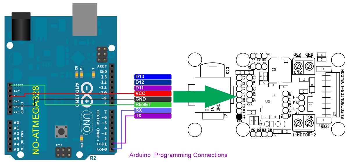
- CN3: Pin 1 TX, Pin 2 = RX, Pin 3 = Reset, Pin 4 = GND, Pin 5 = VCC, Pin 6 D11, Pin 7 = D12, Pin 8 = D13
- CN4: Pin 1 = VCC, Pin 2 = D6, Pin 3 = D7, Pin 4 = D8, Pin 5 = GND
- CN5: Pin 1 = VCC, Pin 2 = A3, Pin 3 = A2, Pin 4 = A1, Pin 5 = GND
- U1: Pin 1 = VCC, Pin 2 = A0, Pin 3 = GND
- U5: Infra-Red Sensor for IR Remote Motor Control Application
- Joy: Joystick Connected to A1 Analog Pin and Joystick Switch Connected to D12 and GND
- D1: Power LED Logic Power
- D4: Power LED Motor Power
- L298 2X Direction Pins = Arduino D9 and D10, L298 PWM/Enable = Arduino D5
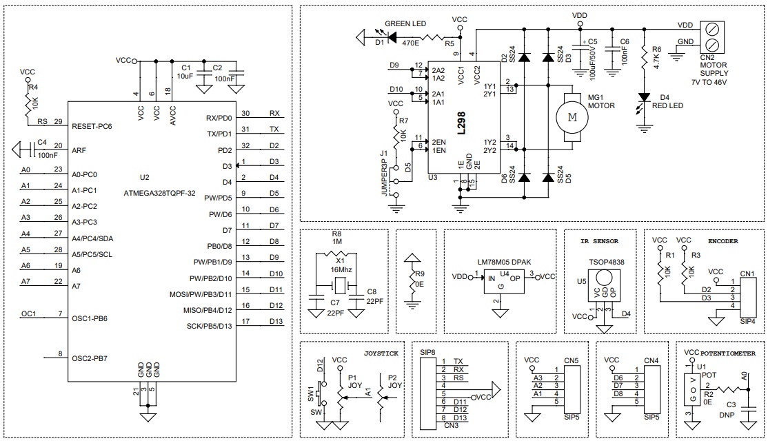
Schematic
Parts List
| NO | QNTY | REF | DESC | MANUFACTURER | SUPPLIER | SUPPLIER PART NO |
|---|---|---|---|---|---|---|
| 1 | 1 | CN1 | 4 PIN MALE HEADER PITCH 2.54MM | WURTH | DIGIKEY | 732-5317-ND |
| 2 | 1 | CN2 | 2 PIN SCREW TERMINAL PITCH 5.08MM | PHOENIX | DIGIKEY | 277-1247-ND |
| 3 | 1 | CN3 | 8 PIN MALE HEADER PITCH 2.54MM | WURTH | DIGIKEY | 732-5321-ND |
| 4 | 2 | CN4,CN5 | 5 PIN MALE HEADER PITCH 2.54MM | WURTH | DIGIKEY | 732-5318-ND |
| 5 | 1 | C1 | 10uF/10V CERAMIC SMD SIZE 0805 | YAGEO/MURATA | DIGIKEY | |
| 6 | 3 | C2,C4,C6 | 100nF/50V CERAMIC SMD SIZE 0805 | YAGEO/MURATA | DIGIKEY | |
| 7 | 1 | C3 | DNP | |||
| 8 | 1 | C5 | 220uF/50V ELECTROLYTIC | PANASONIC | DIGIKEY | PCE3921CT-ND |
| 9 | 1 | SHUNT | SHUNT FOR JUMPER J1 | SULLINS CONNECT | DIGIKEY | S9001-ND |
| 10 | 2 | C7,C8 | 22PF/50V CERMIC SMD SIZE 0805 | YAGEO/MURATA | DIGIKEY | |
| 11 | 1 | D1 | GREEN LED SMD SIZE 0805 | DIALIGHT | DIGIKEY | 350-2044-1-ND |
| 12 | 4 | D2,D3,D5,D6 | SS34 SMD FAST DIODE | TAIWAN SEMI | DIGIKEY | 1801-SS24CT-ND |
| 13 | 1 | D4 | RED LED SMD SIZE 0805 | OSRAM | DIGIKEY | |
| 14 | 1 | J1 | 3 PIN MALE HEADER PITCH 2.54MM | WURTH | DIGIKEY | 732-5316-ND |
| 15 | 1 | MG1 | 2 PIN SCREW TERMINAL PITCH 5.08MM | PHOENIX | DIGIKEY | 277-1247-ND |
| 16 | 2 | P1,P2,SW1 | THUMB JOYSTICK INCLUDING SWITCH | C&K | DIGIKEY | 108-THB001P-ND |
| 17 | 4 | R1,R3,R4,R7 | 10K 5% SMD SIZE 0805 | YAGEO/MURATA | DIGIKEY | |
| 18 | 2 | R2,R9 | 0E SMD SIZE 0805 | YAGEO/MURATA | DIGIKEY | |
| 19 | 1 | R5 | 470E 5% SMD SIZE 0805 | YAGEO/MURATA | DIGIKEY | |
| 20 | 1 | R6 | 4.7K 5% SMD SIZE 0805 | YAGEO/MURATA | DIGIKEY | |
| 21 | 1 | R8 | 1M 5% SMD SIZE 0805 | YAGEO/MURATA | DIGIKEY | |
| 22 | 1 | U1 | 2 PIN SCREW TERMINAL PITCH 5.08MM | PHOENIX | DIGIKEY | 277-1247-ND |
| 23 | 1 | U2 | ATMEGA328TQPF-32 | MICROCHIP | DIGIKEY | ATMEGA328PB-AURCT-ND |
| 24 | 1 | U3 | L298 TO220 11 PIN | ST | DIGIKEY | 497-1395-5-ND |
| 25 | 1 | U4 | LM78M05 DPAK | TI | DIGIKEY | MC78M05CDTGOS-ND |
| 26 | 1 | U5 | TSOP4838 | VISHAY | DIGIKEY | TSOP4838-ND |
| 27 | 1 | X1 | 16Mhz | ECS INC | DIGIKEY | X1103-ND |
Connections
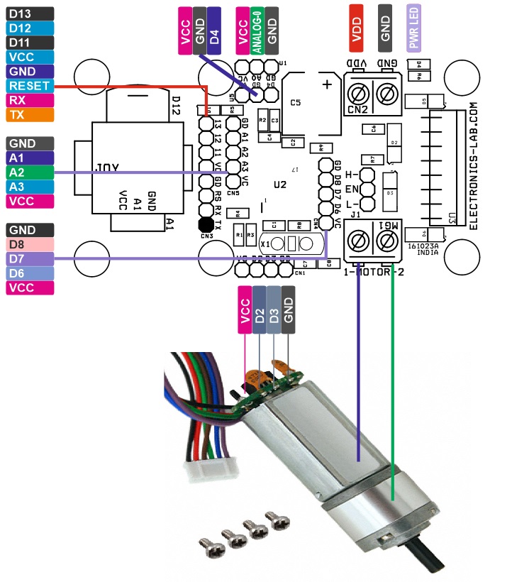
Arduino Connections
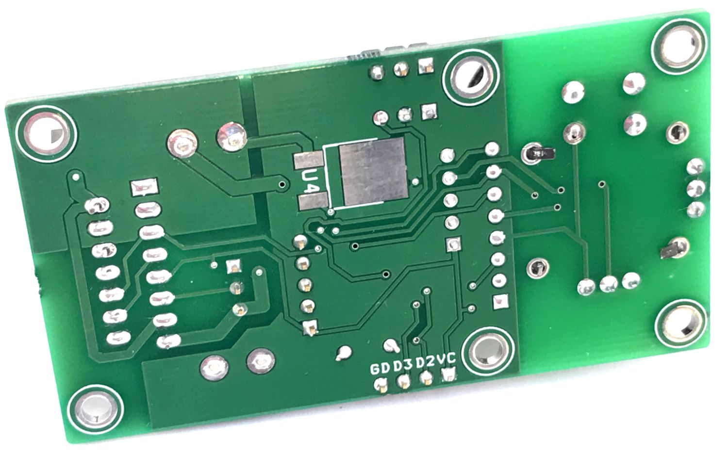
Gerber View
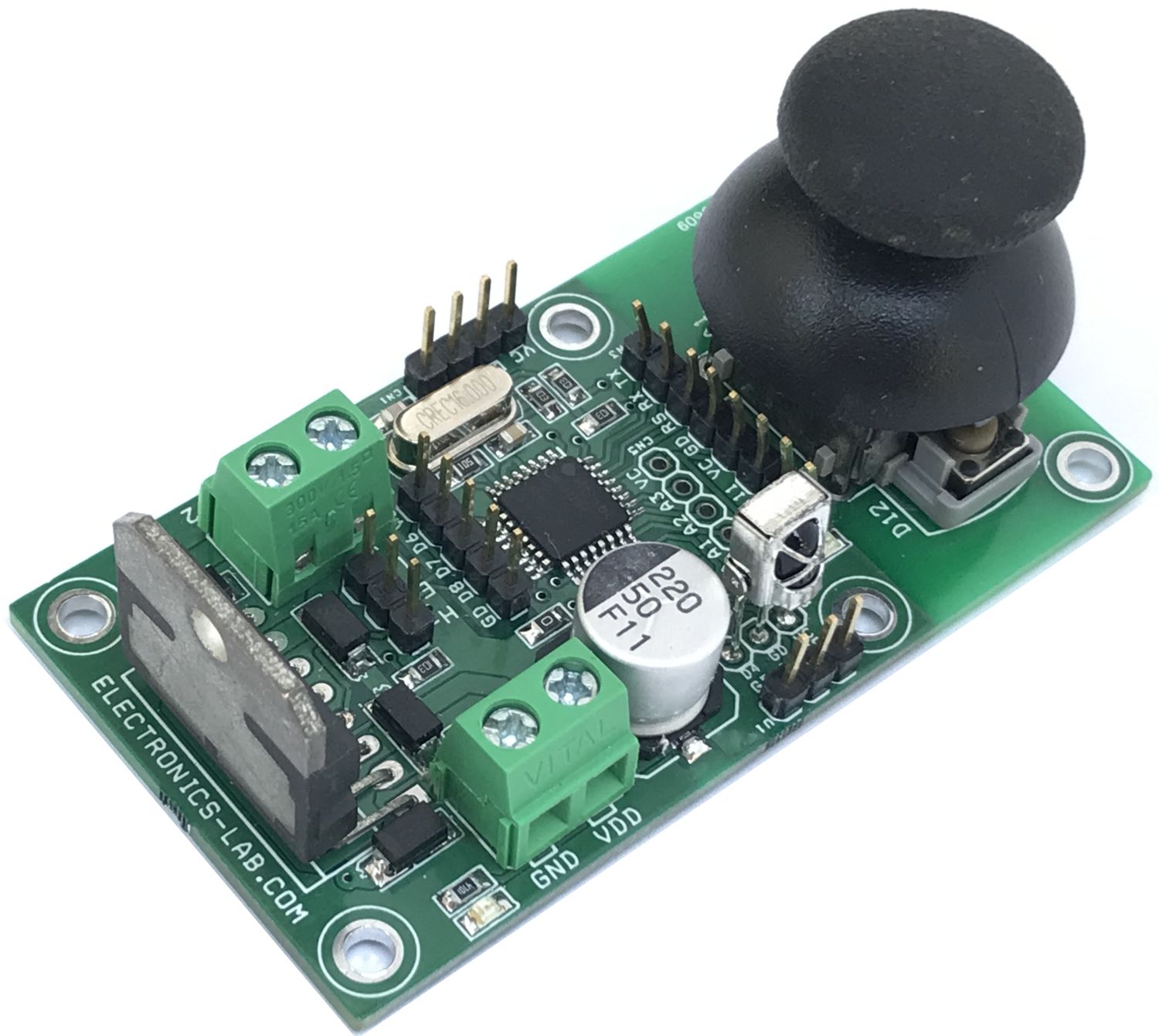
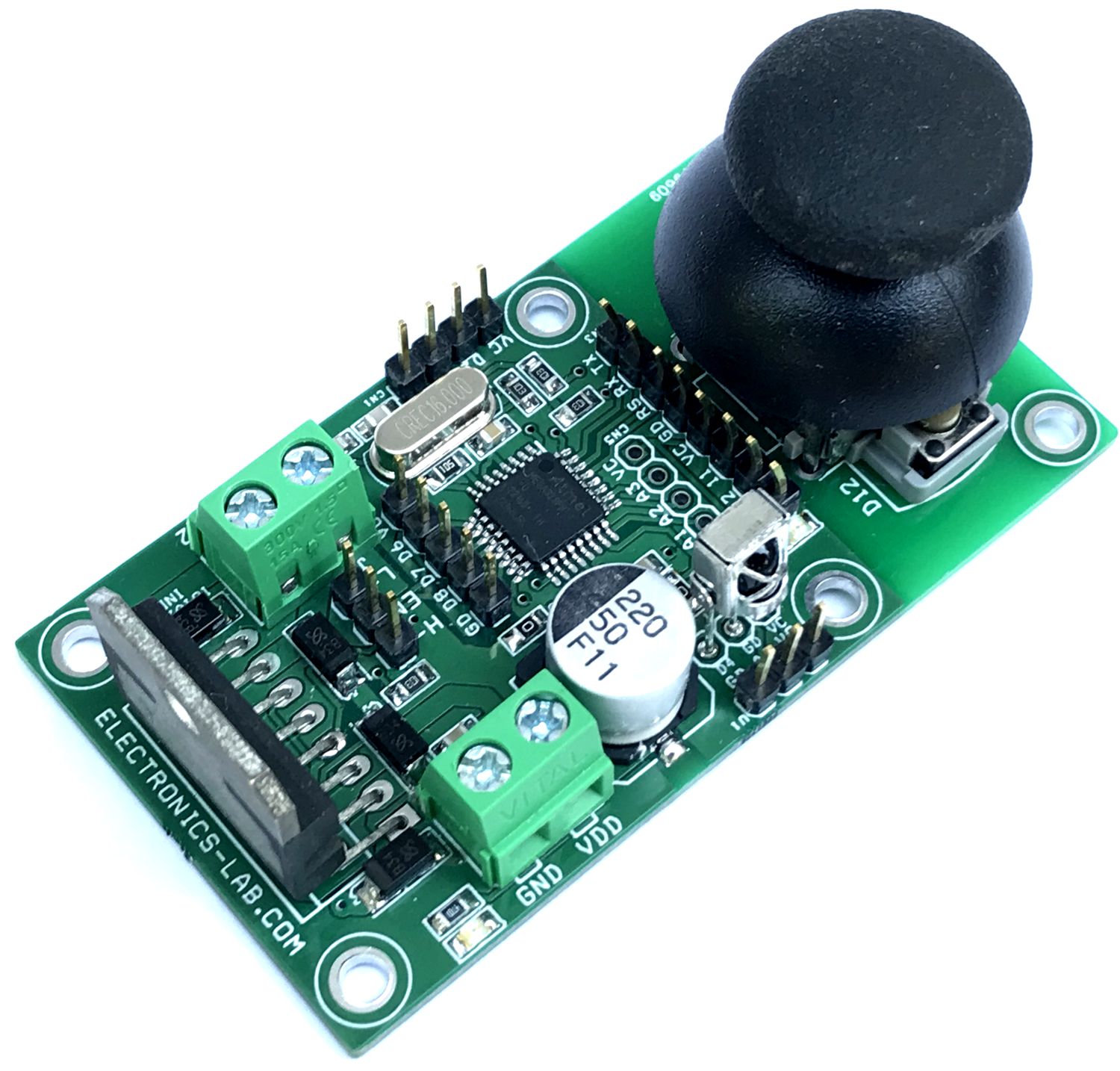
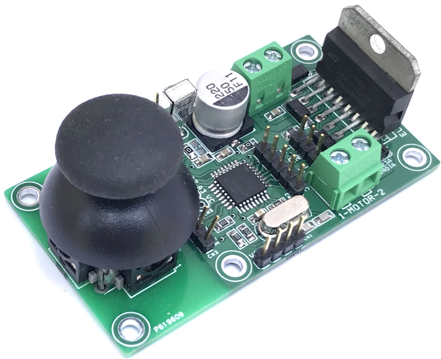
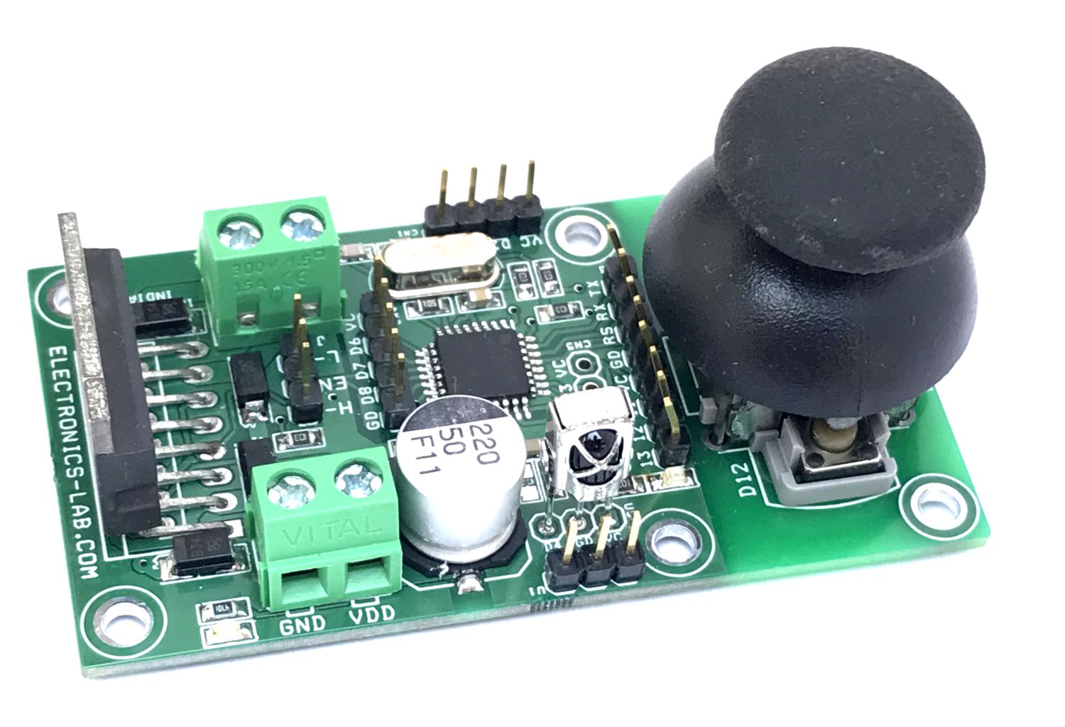
Photos
Video
where is the code link?
Not very useful without the code.
Check this sample code: https://www.electronics-lab.com/wp-content/uploads/2024/01/CODE-2.zip