Getting Started with STM8S using STVD and Cosmic C Compiler
Last time we examined how to program the STM8s microcontroller using the Arduino IDE. This way may work for developers who are familiar with the IDE and want to build quickly, and professional projects, but there are more ways to get the same result.
Last time we examined how to program the STM8s microcontroller using the Arduino IDE. This way may work for developers who are familiar with the IDE and want to build quickly, and professional projects, but there are more ways to get the same result. Thus for today’s tutorial, we are going to examine how to use traditional tools like the Cosmic C compiler along with STVD to program the STM8s microcontrollers.
There are several members of the STM8s microcontroller out there but for this tutorial, we will work with the STM8S103F3P6 microcontroller which is one of the cheapest, and most popular member of the family. The popularity of the STM8S103F3P6 makes it a perfect microcontroller for beginners as you can easily find support for it across several forums on the internet.
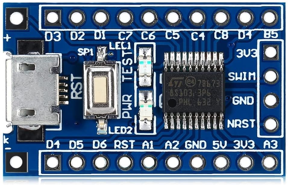
For easy prototyping, we will use the STM8sBlue development board which is essentially a breakout board for the STM8S103F3P6 MCU with a USB interface, breadboard compatibility, and a few other components to facilitate the development of prototypes for projects based on the MCU.
In addition to the STM8sBlue development board, we will need the ST-LINK programmer, preferably the ST-LINK v2 programmer. It will be used to upload firmware from the PC to the microcontroller.
Our goals for today’s tutorial will be to examine how to set up the tools, and for a demo, we will flash the microcontroller with the hardware hello world LED blink example.
Ready? Let’s go
Required Components
The components required to replicate and follow this project includes:
- STM8sBlue development board
- ST-LINK v2 programmer
- Jumper Wires
- Breadboard
- 220 ohms Resistor
- LED
The STM8sBlue and the ST-Link programmer can be bought from the attached links, while others can be easily obtained from your favorite electronics component store. The resistor and LED are only important if you will prefer to use an LED other than the one onboard the STM8sBlue.
Schematics
Asides schematics for folks who will not be using the onboard LED, the only schematics associated with this project is for the connection between the STM8sblue and the ST-Link V2 programmer. Connect both of them as shown in the schematics below:
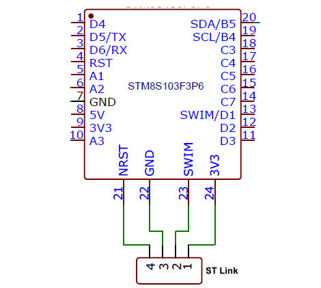
A pin-pin map showing how the ST-Link V2 is connected to the dev board is also provided below to make the connection easy to follow.
ST-Link V2 –STM8S103F3
1(3.3v) - 3v3
2(SWIM) - SWIM
3(GND) - GND
4(RST) - NRST
With this done, we can now proceed to set up the software side of the project.
Install the Cosmic C compiler and STVD
To program the microcontroller, we need an IDE and a compiler. As mentioned during the introduction, we will use the Cosmic C compiler and the ST Visual Develop (STVD) IDE. Unfortunately, both software is only available in the Windows OS version so you will need a windows based machine or a partition to install and use them.
Head over to Cosmic and ST websites and download the software. Both software is free to use and will only require you to sign up on the websites to download.
With both software downloaded, run the installation, following the on-screen instructions displayed by the setup wizard. The STVD IDE should install without a fuss, but the Cosmic C compiler will request that you get a free license key, with a prompt that asks for your email address.
The prompt is displayed after a readme file that contains guidelines on use, is closed.
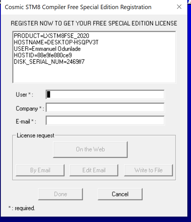
Fill the information requested by the prompt, select the “On the Web” option (if you are connected to the internet), and click on done. This should launch a webpage where you will be required to enter your email address again if not auto-filled. With these complete, you should get a license request processed notification, and receive the license key in your email, a few minutes after submitting the request. Due to spam algorithms, the license email may be “quarantined” in the spam section of your email box. Make sure also to check there.
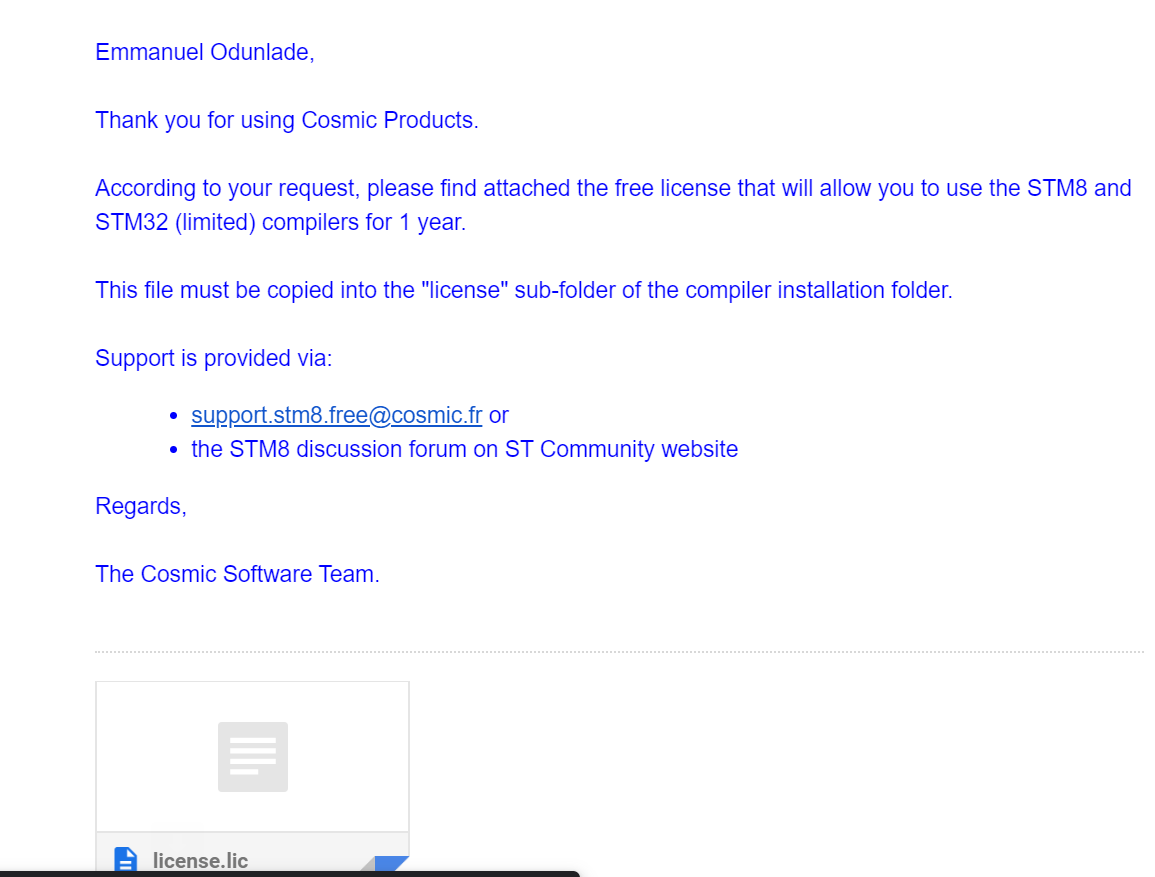
With the license file received, follow the installation instruction, and copy the license.lic file to the “license” sub-folder of the COSMIC installation folder on your computer. In my case the license sub-folder was located at this path: “C:\Program Files (x86)\COSMIC\FSE_Compilers\CXSTM8\License“.
With this done, both software should now be fully installed and ready for use.
One other thing we need, that is probably better to also get at this stage, is the Standard Peripheral Library for the STM8S103F3P6 microcontroller. The library can be downloaded from ST’s website, but for simplicity and ease of use, this nicely modified library by Circuit Digest’s Aswinth Raj might be a better version.
With all these in place, we can now proceed to use these tools to develop the code for our project.
Code
To write the firmware, we need to create a new project specifying the microcontroller for which the firmware is to be developed and the destination folder where all project files will be store. Follow the steps below to do this:
Start by opening STVD and select File -> WorkSpace, in the pop-up, select “New Workspace” and enter the Project name and path where the program should be saved. I am naming my program BareMinimum and saving it in a folder on the desktop. Click OK and you will get the New Project dialog box as shown below.
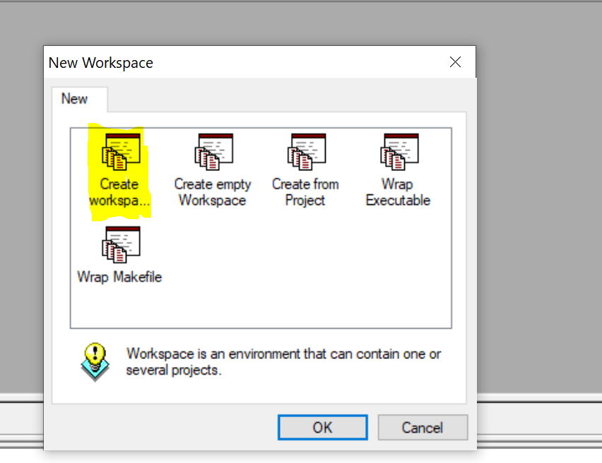
1. Open the Installed ST Visual Develop and go to File -> “New Workspace” to create a new workspace.
2. On the resulting pop-up box, select the “Create a Workspace and Project” option highlighted in the image below.
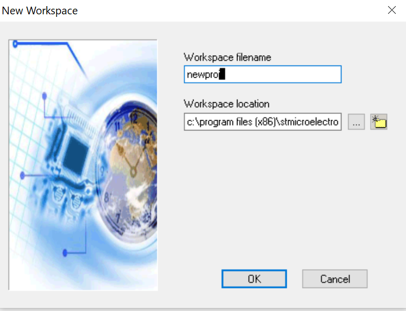
3. On the next window, enter your preferred workspace name. I will be calling this “newproj” and will save it in the default location. Click OK when done.
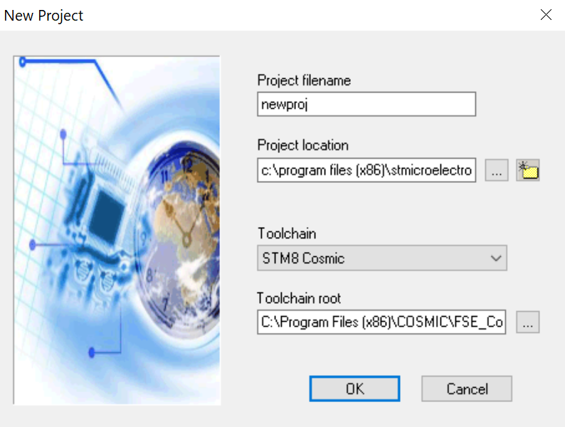
4. The next window will require you to provide a project filename, preferred storage location, the toolchain to be used, and the root address to the toolchain. For me, the project name will be newproj, and the directory will be the default. We will use the Cosmic C compiler so you should set the toolchain as STM8 Cosmic and the toolchain root should be the path where your Cosmic compiler was installed. The default path address is “C:\Program Files (x86)\COSMIC\FSE_Compilers\CXSTM8” and should also be the path on your machine if it was not changed during installation. You can also use the folder button to navigate to the CXSTM8 folder.
5. After clicking OK above, the MCU selection window will come up. Fill as shown in the image below, selecting the STM8s103F3P microcontroller.
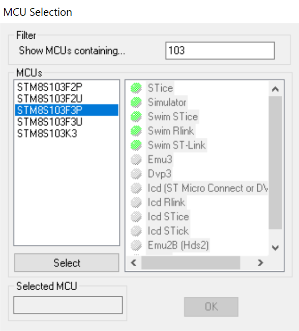
You can quickly search for the microcontroller by typing its name in the search bar. With this done, click OK. You should now be able to see the STVD workspace.
6. Next, we need to add the SPL libraries we downloaded to the project files. To do this, expand the project folder (newproj) in the workspace, right-click on the “Source files” folder and click on the “add files to folder” option and navigate to the “src” folder in the library we downloaded. select all the “.c” files in the folder and add them.
7. Next, we need to also add the header files. Right-click on the “include files” folder on the workspace, and select “Add files to folder“. Navigate to the “inc” folder of the library we downloaded and add all the “.h” files.
8. Verify library addition and general setup by building. Click on the “build” button and select “rebuild all” followed by the “compile” button.
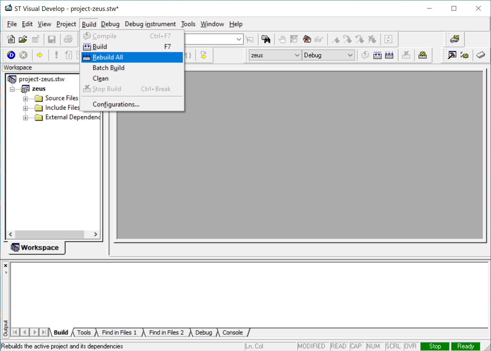
If the build is successful, you should see “zero build errors” displayed on the command line like in the image below.
With this done you are now ready to start writing the code for our project.
As mentioned earlier, the code for today’s project will be to blink the onboard LED at certain intervals. As with all our projects, I will do a brief explanation of the code and provide the complete code at the end.
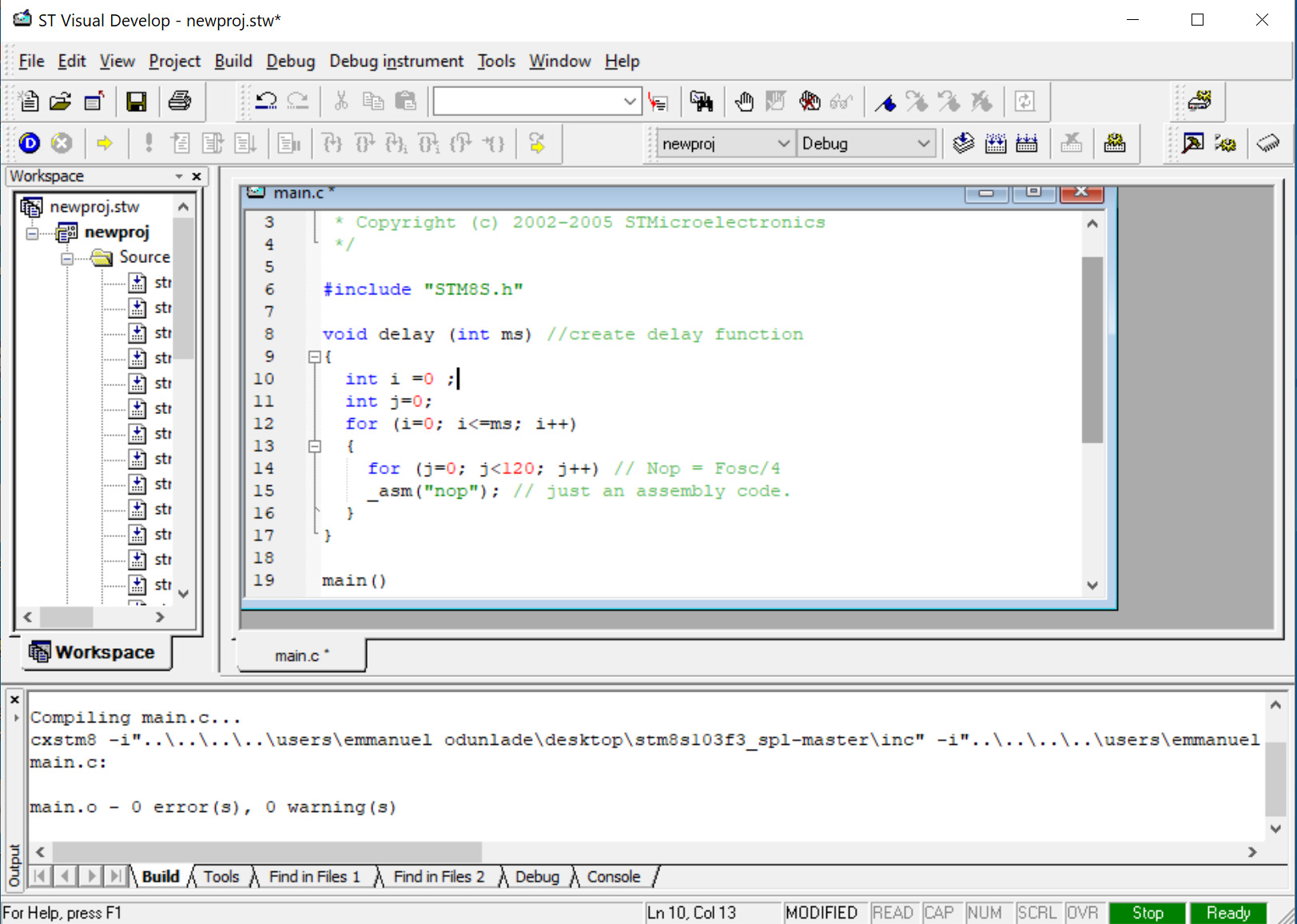
The code will be written in the main.c file which is automatically generated when you create a new project. We start the code by including the STM8s library, which helps adds some level of code IntelliSense to our project.
#include "STM8S.h"
Next, we write the delay function. Unlike with the Arduino where the functions are pre-written and we just call them to use, here you have to write most of the functions your self. The delay function will be used to indicate how long the led stays in a particular state before switching to the other state.
void delay (int ms) //create delay function
{
int i =0 ;
int j=0;
for (i=0; i<=ms; i++)
{
for (j=0; j<120; j++) // Nop = Fosc/4
_asm("nop"); //Perform no operation //assembly code <span style="white-space:pre"> </span>
}
}
Next, we write the main function. We start by deinitializing Port B, i.e., the port to which the pin of the onboard led is associated. While deinitializing the port is not mandatory, it helps totally free up the port from whatever function it was used for before, ensuring your project is hitch-free.
main()
{
GPIO_DeInit(GPIOB); // deinitialize port B
Next, we declare the pin to which the onboard led is connected as a push-pull output pin with default low status.
GPIO_Init (GPIOB, GPIO_PIN_5, GPIO_MODE_OUT_PP_LOW_SLOW); //Declare PB5 asa default low push-pull output pin
Finally, we write the while loop function. Here we basically place the code to turn ON and OFF the onboard led. For this, we will use the GPIO_WriteReverse() function which reverses the state of the pin. So if it was on before, it turns it OFF, and vice versa. We will also add a delay of 200ms to allow us to see the blink without the eye’s persistence effect.
while (1)
{
GPIO_WriteReverse(GPIOB,GPIO_PIN_5);
delay (200);
}
}
The complete code for the project is provided below;
/* MAIN.C file
 *
 * Copyright (c) 2002-2005 STMicroelectronics
 */

#include "STM8S.h"

void delay (int ms) //create delay function
{
  int i =0 ;
  int j=0;
  for (i=0; i<=ms; i++)
  {
    for (j=0; j<120; j++) // Nop = Fosc/4
    _asm("nop"); // just an assembly code.
  }
}

main()
{
  GPIO_DeInit(GPIOB); // deinitialize port B

  GPIO_Init (GPIOB, GPIO_PIN_5, GPIO_MODE_OUT_PP_LOW_SLOW);
  //Declare PB5 as a default low push-pull output pin

  while (1);
  {
    GPIO_WriteReverse(GPIOB,GPIO_PIN_5);
    delay (100);
  }
}
Uploading the Code
With the code complete, its time to hook up your board to your computer and upload the code. The process of uploading code to the board is not as straight forward as with the Arduino IDE but its easy to follow and should become seamless once you get the hang of it.
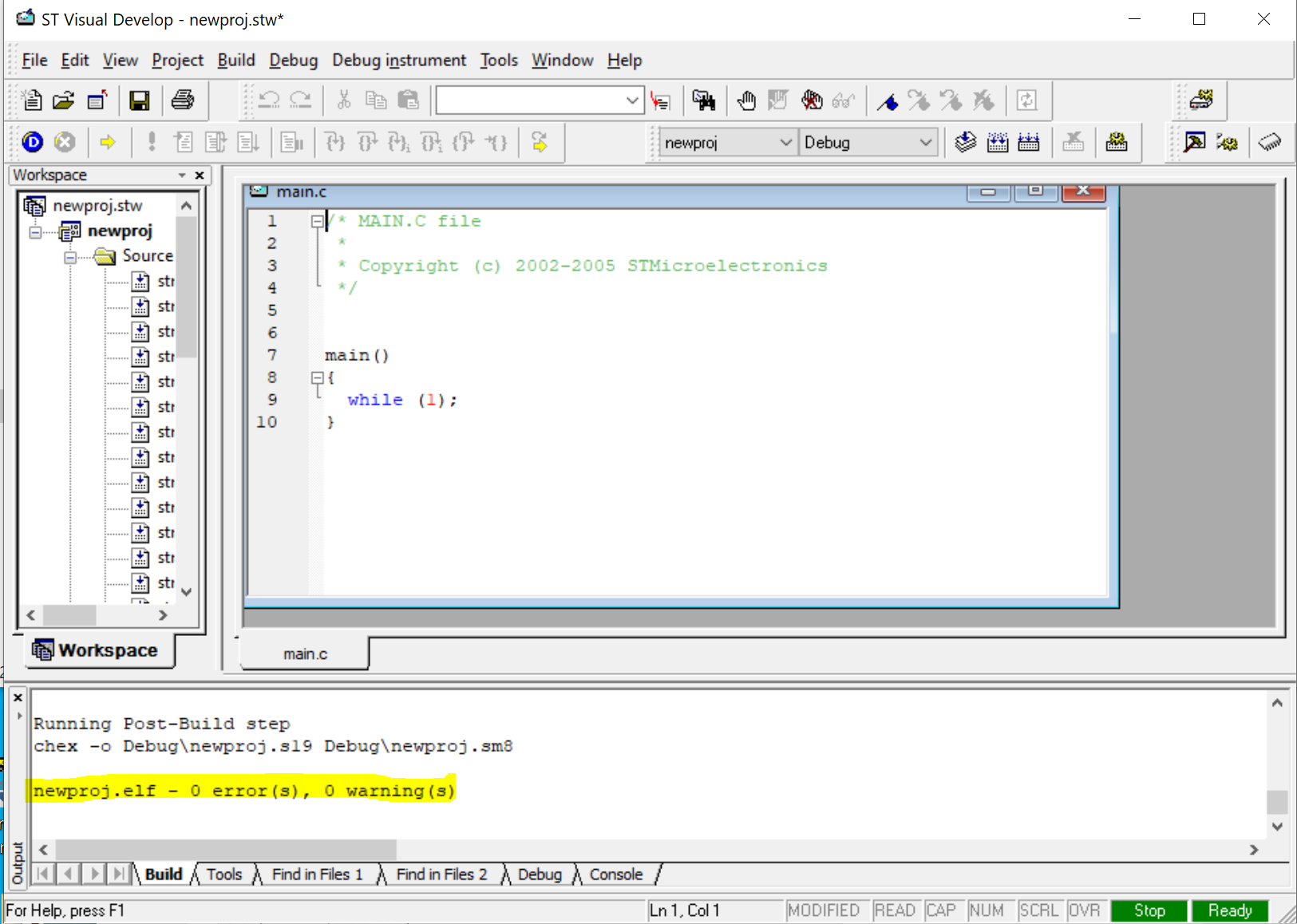
Once the code is complete, click on the Build -> rebuild all and ensure there are no errors. If everything is fine, it should return the “0 errors and o warnings” line. With this done, hit the Compile button. If there are no errors, the program should compile easily and you should see the “0 errors and 0 warnings” in compile success line.
With the successful compiling, a “.s19” file will be generated under the debug directory of the project’s folder. This file is similar to the Hex file and it’s what you will upload to the microcontroller. To upload the .s19 file to the microcontroller we will use the ST Visual Programmer (STVP) which would have been installed alongside STVD.
When opened, the STVP presents the configuration page shown below. Select the programmer, the programming mode, and the device/microcontroller which in this case are ST-Link, SWIM, and STM8s103F3 respectively.
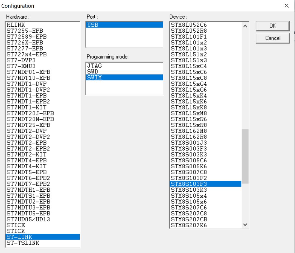
Hit the OK button when complete. This should launch the STVP interface.
Click on “file->Open” and navigate to the debug folder where you have the .s19 file we generated earlier and open it. Click on “Program” and select “Current Tab“. These should begin the flashing process and the firmware should now be loaded on your microcontroller. If successful, you should see the following line on the command prompt area of the software:
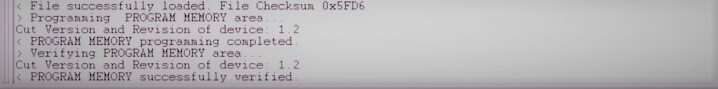
and the LED on the STM8sblue should also start blinking at a pace equal to the 200ms we specified.
It is probably important to note that before launching the STVP, you should connect the microcontroller via the ST-link to your computer. If you are using the ST-Link for the first time, the device driver will automatically be installed on your PC. If this is not the case you might need to run a quick google search to find out the requirements for your computer.
That’s it, folks! There you have it. If you have any challenges with any part of the project, do reach out to me via the comment section. I will be happy to help.
Thank you very much for this clear and understandable education. I can say that it was very useful for me. I wish you success in your work.