Indoor Air Quality Monitoring System
I'm quite passionate about air quality monitoring, so whenever I see an interesting air quality monitoring project that could help people stay healthy, while also serving as a good way to learn DIY electronics, I'm always eager to share. Thus, for today's tutorial, I will chronicle the build process of an Indoor Air Quality Monitoring system developed and shared on Hackster by Roman Novosad.
I’m quite passionate about air quality monitoring, so whenever I see an interesting air quality monitoring project that could help people stay healthy, while also serving as a good way to learn DIY electronics, I’m always eager to share. Thus, for today’s tutorial, I will chronicle the build process of an Indoor Air Quality Monitoring system developed and shared on Hackster by Roman Novosad.
The device developed by Roman determines air quality by monitoring and displaying the amount of CO2, TVOC, and particulate matter in the air. It also monitors other parameters like air pressure, temperature, and humidity to ensure that the user is aware of their environment at all times. Unlike most air quality monitoring solutions, Roman’s project is designed for indoor use, which if we all think about it, is quite important as people typically spend 60 percent of their time indoors, and can directly influence the conditions to make it more conducive, unlike in outdoor situations.
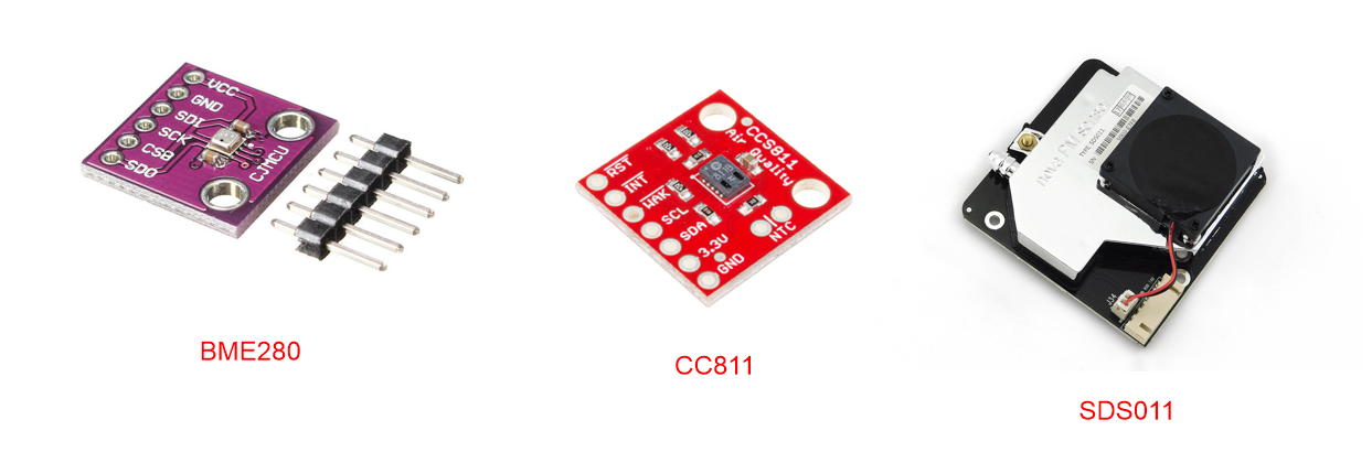
The project makes use of high-quality sensitive sensors like the BME280, the CC811, and the SDS011. The BME280 is used to monitor the temperature, humidity, and atmospheric pressure in the environment while CC811 is used to measure the amount of CO2 and the total amount of volatile compounds (TVOC) in the environment. The SDS011 is used to monitor particulate matter ( PM2.5 and PM10), and data from all the sensors are displayed on a 5″ touch-screen, to provide visual feedback to users.
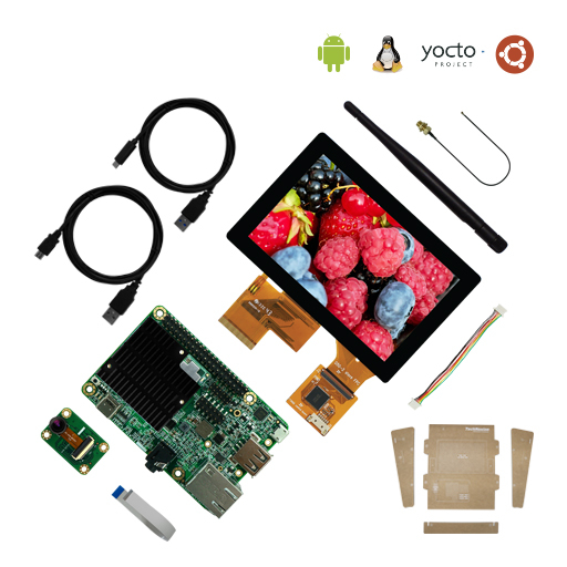
To process the information from the sensors and display them, the project makes use of the NXP i.MX7 SOM based PICO-Pi-i.MX7 from Wandaboards. The Pico-PI-iMX7, thanks to the i.MX7 features a dual-core processor comprising of the ARM Cortex A7 and Cortex M4 processors. The board maintains a pin-out arrangement and form factor similar to that of the Raspberry Pi and possesses communication features like WiFi, Bluetooth, and Ethernet among others. A datasheet listing all the features of the board. To make the board easy to use, Wandaboard packages it as a kit with a display and other useful accessories. The kit is what will be used for today’s tutorial.
At the end of this tutorial, alongside being able to replicate the project, you would have learned how to work with a board like the Pico-pi-i.MX7 and also use some of the sensors.
Required Components
As mentioned above, the following components are required to build this project;
- Wandboard PICO-PI-IMX7-START KIT
- Sparkfun BME280 Breakout
- Sparkfun CCS811 Air Quality sensor Breakout
- Nova PM SDS011 Dust sensor
- Jumper Wires
- Breadboard
- Enclosure
- Tape/Screws (M2.5)/Hot Glue
All components can be bought from the links attached to them.
For the enclosure, while Roman created one for the project, you can decide to design yours and choose an attachment option (number 8 above) that suits you. If you will, however, use the enclosure designed by Roman, then ensure to get the M2.5 screws along with other components.
Asides the hardware components, the project also has some software requirements which include having an Android Studio installed on your computer as it will be used in uploading the software to the board.
Schematics
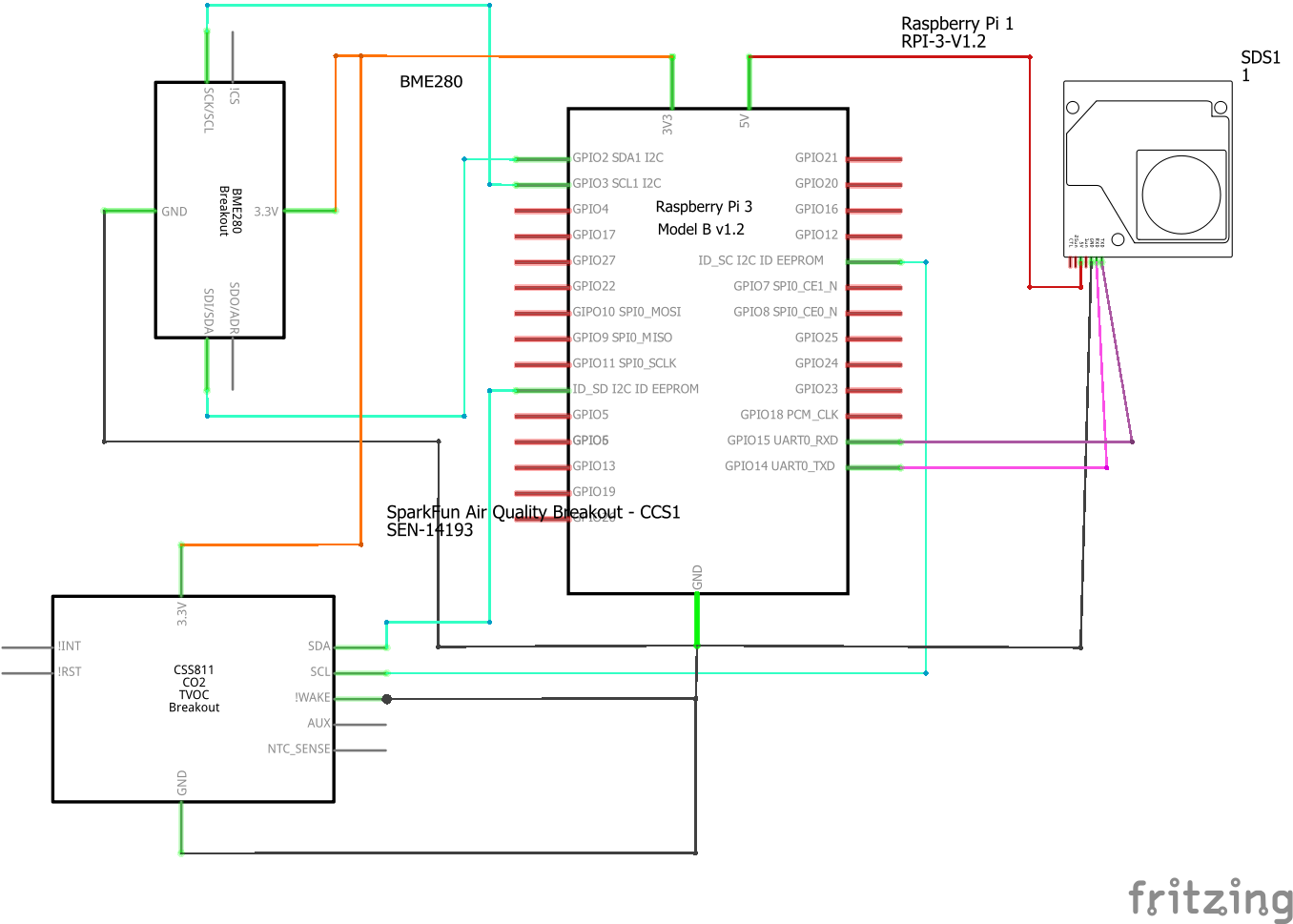
Connect the sensors to the Pico-Pi-i.MX7 as shown in the image below.
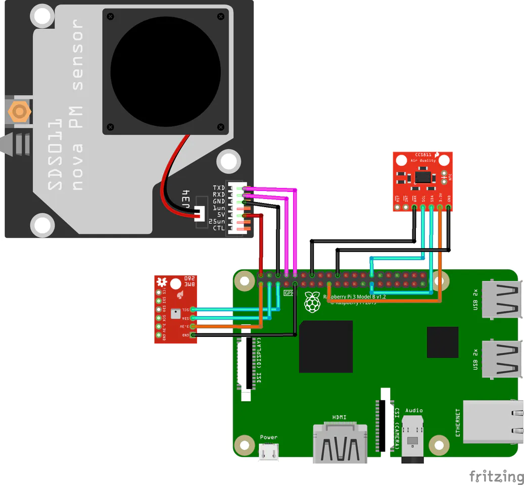
Notice the Raspberry Pi was used in the schematics? A model for the Pico-Pi-i.MX7 is not available on fritzing, so, the one for the Raspberry Pi was used since the iMX7 and the PI share the same pinout configuration. To get a better understanding of the connections and verify the relationship between the pinout of the Raspberry Pi and iMX17, you can check out this description of the iMX17 board.
To make the schematics easier to follow, another view of the connection is provided below:
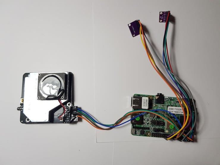
After connecting the sensors, the setup should look like the image below.
With everything in place, connect the other accessories(screen, etc.,) to the Pico-Pi. The setup after this has been done should look like the image below;
With this done, we are now ready to FLASH the device with the project’s firmware.
Install the software
The IMX7 SOM comes with the Android Things OS preloaded out of the box, as such, the easy path to programming the board is via Android Studio. So if you are yet to install it, now it will be a good time to do that.
With your Android Studio installed, plug the USB Cable to the Pico-Pi and to your computer. The Pico-Pi should begin its boot process and when complete, you should see a screen that tells you the device name and the wireless network to which it is connected (even though that is not needed for this tutorial).
The software for the project is already precompiled as an application by Roman, so all we need to do is to install that software on the Pico-Pi-i.MX7. However, before the application is installed, it is important to ensure no other application has been previously installed on the Pico-Pi.
You can check if a previous application has been installed, you can uninstall it (using a Windows computer) by:
- Accessing
C:\Users\,<YOUR_USER>\AppData\Local\Android\Sdk\platform-tools>via cmd - Then type
adb rootto get root access to the IMX7. - Next, run
adb shell, followed bycd data/appandlsto see all the packages installed on the machine. - If there is an application installed, Copy the name (i.e. everything before the “-“) and Type
exit. - Next, uninstall the app you discovered by typing
adb uninstall <NAME_YOU_COPIED>.
With this done, the existing app would be uninstalled and you can proceed with installing the App by Roman.
To install the needed APP, launch Android Studio on your PC and load the app files into your workspace by accessing them from the projects GitHub page via version control.
With the app loaded, Android Studio should automatically detect the connected Pico-Pi-i.MX7 board and you should be able to run the project on it by pressing ‘Run’. When you do this and the project runs successfully, the app will be installed on the Pico Pi and will stay on it even if you disconnect the SOM from the computer.
Demo
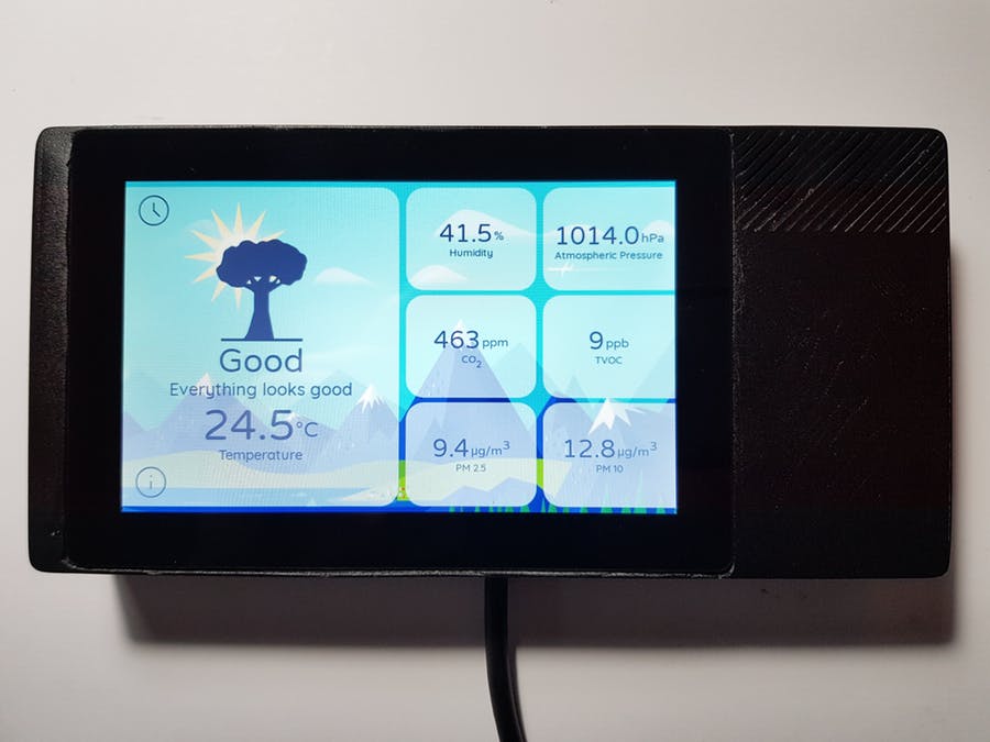
With the App installed, disconnect the device from the computer and power using a battery or over USB. You should see the device boot up and the screen comes up with the sensor values as shown in the image below.
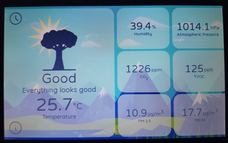
The values of CO2 and TVOC may vary arbitrarily initially, but after a while, it should settle and become consistent.
By default, the screen is updated with sensor data every (1) second but you can change this option on the screen to increase the time by clicking on the clock icon. You can also choose to see more information about the measurement among other things by clicking the information icon.
Enclosure
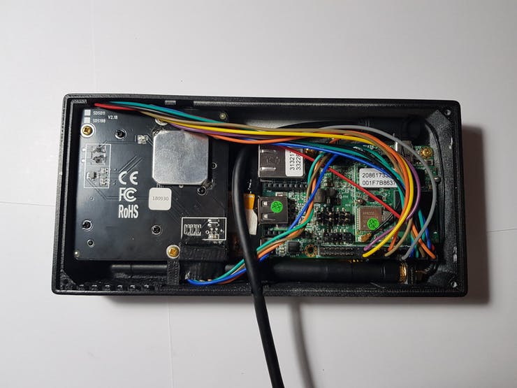
To make the project compact and pleasing to the eyes, Roman created a 3D printed enclosure for the project. The design and STL Files are attached under the download section below. Feel free to modify to suit your taste. The device after assembling in the enclosure is shown in the image below.
That’s it! Your very own Indoor Air Quality Monitor.
There are different modifications that could be made to this project. You could decide to add alarms with a buzzer, or connect the device to the internet to send you an email alert, or even populate an online dashboard. However, in the coming weeks, I will be creating an ESP32/Raspberry pi based version of the project with micro python since that is more popular and may be easier to manipulate. If you are interested in that version of the project drop a comment saying so!
Very cool. I would be interested in seeing a Pi based equivalent.
Thanks.
do you have please this project
hi please i m interessted to the next project with python i need this project plz