Program ATtiny 0-Series Chips with a Miniature UPDI Dongle
Thanks to their tiny size and improved capabilities, the ATtiny-0-Series of microcontrollers have been a delight for designers and DIYers looking for a microcontroller with the ease of use associated with the Arduino boards, but with a way smaller form factor associated with ATtiny microcontrollers. Along with the ATtiny-1-series, the ATtiny-0-Series microcontrollers were meant to serve as a modern replacement for other popular ATtiny chips like the ATtiny85 and ATtiny45.
Thanks to their tiny size and improved capabilities, the ATtiny-0-Series of microcontrollers have been a delight for designers and DIYers looking for a microcontroller with the ease of use associated with the Arduino boards, but with a way smaller form factor associated with ATtiny microcontrollers. Along with the ATtiny-1-series, the ATtiny-0-Series microcontrollers were meant to serve as a modern replacement for other popular ATtiny chips like the ATtiny85 and ATtiny45. While they have been able to do these with incredible features one challenge users have had over time includes; difficulties in programming the chips, as, unlike the previous ATtiny chips, they use a not so popular programming protocol called UPDI in place of the ISP protocol used by the previous series.
To solve this, several programmers have developed various ways through which the Attiny-0-series can be programmed. One of them was discussed in one of our previous tutorials, but for today’s tutorial, we will look at the most elegant way we have seen so far; the UPDI Programming Stick developed by David Johnson-Davies.
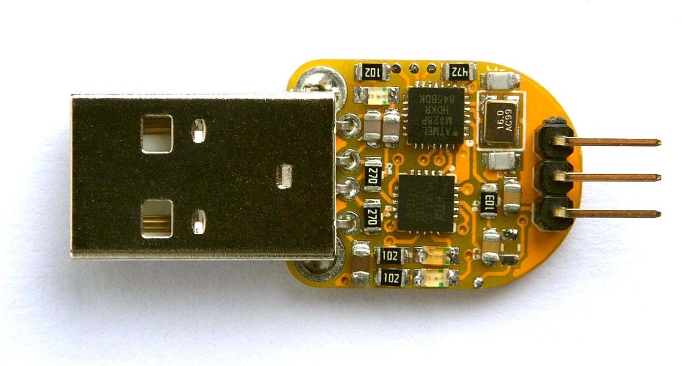
This programmer is based on the Atmega328P and can really be said to be an Arduino Uno on USB. It uses the Atmega328P microcontroller as the UPDI programmer while the FT231 serves as the USB to UART converter facilitating data exchanges between the programmer and the computer. As mentioned above, the device can also be used as a limited Arduino Uno, for the reason that the digital pin 6 of the Atmega328P which is compatible with the pin 6 on an Arduino Uno, is broken out so it can be used for Arduino related acts.
While the programmer can be bought from different electronics component online stores, the maker in us would love to build our own and since the design is open-source we have all we need.
Thus for today’s tutorial, we will examine how you can build your own version of the UPDI Programmer stick.
Required Components
Since the idea behind the project is to make a solid board, the project is implemented on a PCB and to reduce the size, most of the components used were SMD, with the USB Male-type connector being the only through-hole component. The components used are provided in the table below;
| Qty | Item | Value | Size | Typical parts |
| 1 | USB Interface | FT231XQ-R | QFN 20 | FT231XQ-R on Farnell |
| 1 | Microcontroller | ATmega328P | QFN 28 | ATmega328P on Farnell |
| 2 | Resistor | 27Ω | 0805 | |
| 3 | Resistor | 1kΩ | 0805 | |
| 3 | Resistor | 4.7kΩ | 0805 | |
| 1 | Resistor | 10kΩ | 0805 | |
| 1 | Resistor | 0Ω | 0805 | Or a wire |
| 2 | Capacitor | 18pF | 0805 | |
| 2 | Capacitor | 47pF | 0805 | |
| 2 | Capacitor | 100nF | 0805 | |
| 1 | Capacitor | 10µF | 0805 | |
| 1 | Crystal | 16MHz 18pF | 3.2 x 2.5mm | ABM8-16MHz on Farnell |
| 3 | LEDs | Red, Green, Yellow | 0805 | |
| 1 | Header | 1×3 Male | 0.1″ pitch | |
| 1 | Plug | USB Male Type A | Through Hole | USB Male Type A Connector on SparkFun |
| 1 | PCB | Double-sided | 16.5 x 21.6 mm |
The fact that most of the components listed above are SMD, means, to be able to build the project successfully, it is important that you have all you need for SMD Soldering, including the tools (like a reflow oven/Hot air gun), skill and experience, especially when it comes to soldering the QFN package components. For those who do not have access to SMD soldering requirements, the Breadboard version of the project can also be built using a through-hole version of the components.
Schematics
The schematic for the project is provided in the image below:
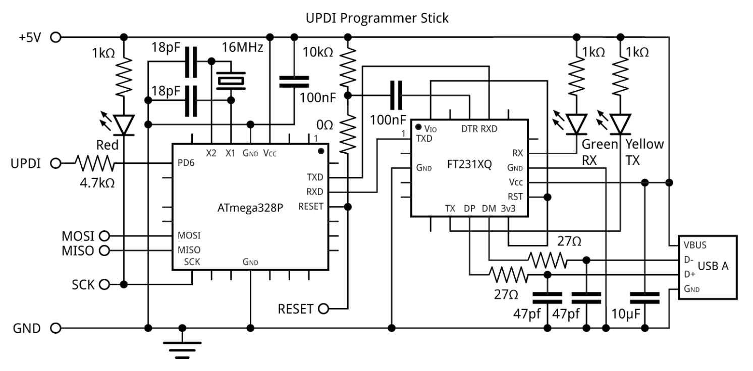
It features two main ICs: the Atmega328p microcontroller and the FT231 USB to UART Converter. The ATmega328p acts as the UPDI programmer and the FT231 FTDI Chip serve as the USB to UART converter, converting the USB signals from the PC to UART for the ATmega328p and vice versa. One of the key design considerations implemented on the board is the creation of three extra pads along with the UPDI Programming pins on the edge of the board. The extra pins provide the user with an ISP port through which users can upload a bootloader to the ATmega328p.
The project files including; schematics, PCB and Gerber files were created using Eagle CAD and all the files for it are attached under the download section.
Assembling Tips
SMD Soldering is a tricky task for both beginners and experts alike and it becomes even more tricky with QFN Package components. To reduce the chances of errors with the QFN Package components, David made suggestions on how to go with the soldering. He described a procedure that involves the use of illuminated magnifying glass. First, put a small blob of solder paste on each pad and then position the components using a pair of tweezers. With that done, the components are heated with a Youyue 858D+ hot air gun at about 250°C until you can see molten solder glistening around the border of the component. Let it cool off and the component should now be firmly attached to the board. The same procedure can be adopted for the other SMD Components while the header pins and USB can be soldered using a normal soldering iron.
The compact nature of the board means the components are quite tight. Ensure they don’t end up a touch after soldering and if necessary, reheat the board and move them apart slightly to ensure no bridge.
Software
While the ATTiny-0-Series programmer can be flashed using several tools like Atmel Studio among others, we understand the average maker wants to be able to write code for them, just like with the Arduino code. As a result of this, we will keep the focus on programming it with the Arduino IDE. Like with every board/microcontroller, programming with the Arduino IDE requires an Arduino Core. This requirement has been sorted for the ATtiny-0-series with the new Arduino core for the new ATtiny chips, developed by Spence Konde and his collaborators, called megaTinyCore.
Setting up the megaTinyCore on the Arduino IDE is described in our previous tutorial where we also described how you can create a makeshift UPDI programmer by running ELTangas’s jtag2updi code on an Arduino Uno or Due. This same Jtag2updi code is the same code that we will upload to our build via ISP to transform it into a UPDI programmer as it also runs the ATmeg328p microcontroller, the same as the Arduino Uno. However, before the software can be uploaded, we need to install a bootloader on our board so it can be programmed with the Arduino IDE. Follow the steps below to install the bootloader.
Installing the Bootloader
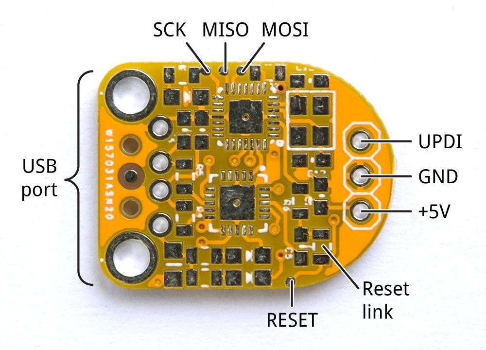
1. Solder a wire link in the position of the 0Ω resistor on the board. This connects the reset line to the microcontroller.
2. Solder wires to the MOSI, MISO, SCK, and RESET pads on the board, and connect these to header sockets that you can connect leads to. I recommend using very fine wires for the connections, so you don’t inadvertently lift the pads off the PCB. The other option is to solder header pins directly to the board.
3. Connect a 3-pin header to the three terminals at the top of the UPDI programmer PCB so you can use this to connect GND and 5V to the board.
4. Connect an ISP programmer to the board via the six wires you have provided. Do note that this could be an Arduino board like the UNO.
5. In the Arduino IDE choose Arduino/Genuino Uno from the Arduino AVR Boards section on the Boards menu, and set the Programmer to ArduinoISP if using the Arduino UNO or to the corresponding programmer name if using any other programmer.
6. Select the Port to which the Programmer is connected and Choose Burn Bootloader to upload the bootloader to the board.
Test the bootloader
With this successfully finished, you should now have the bootloader installed on the UPDI Programmer. You can test the success of the bootloader flashing process by uploading the Arduino Blink example to the UPDI Programmer via the USB port. Launch the example by going to File -> Examples -> Basic -> Blink. Select the board type, along with the port to which the board is connected. Hit the upload button and if all is well the red LED should flash on the UPDI Programmer Stick. If this fails, make sure you’ve uploaded a bootloader as described in the previous steps.
With the bootloader tested, the next task is to upload the jtag2updi code to the board.
Upload the UPDI Programmer Sketch(jtag2updi)
Follow the steps below to upload the jtag2updi programmer sketch to the UPDI Programmer stick.
- Download the UPDI programmer sketch
- Extract the zip file and open the jtag2updi folder.
- Open the jtag2updi.ino sketch with the Arduino IDE, connect the UPDI Programmer stick to your computer via USB and upload the code just like you did for the blink sketch above.
- Remove the wire you fitted earlier in the 0Ω resistor position on the UPDI Programmer board
That’s it, the board is now ready to be used as a UPDI Programmer but we have one more step to take. The UPDI is a protocol that is not part of the list of the programmer protocols that were shipped with the Arduino IDE. As such, for the Arduino IDE to recognize the board as a programmer, the megaTinyCore needs to be installed in the IDE. Steps to installing the megaTinyCore have already been covered in our last tutorial, in which we examined how you can turn an Arduino nano into a UPDI Programmer. You can follow those steps to install the megaTinyCore on the Arduino IDE.
Programming the Chips with the UPDI Programmer
The UPDI Programmer stick is ready and the Arduino IDE is ready for UPDI Programming. Follow the steps below to program your ATtiny-0-series microcontroller.
1. Connect the ATtiny to the UPDI Programmer stick as shown in the image below: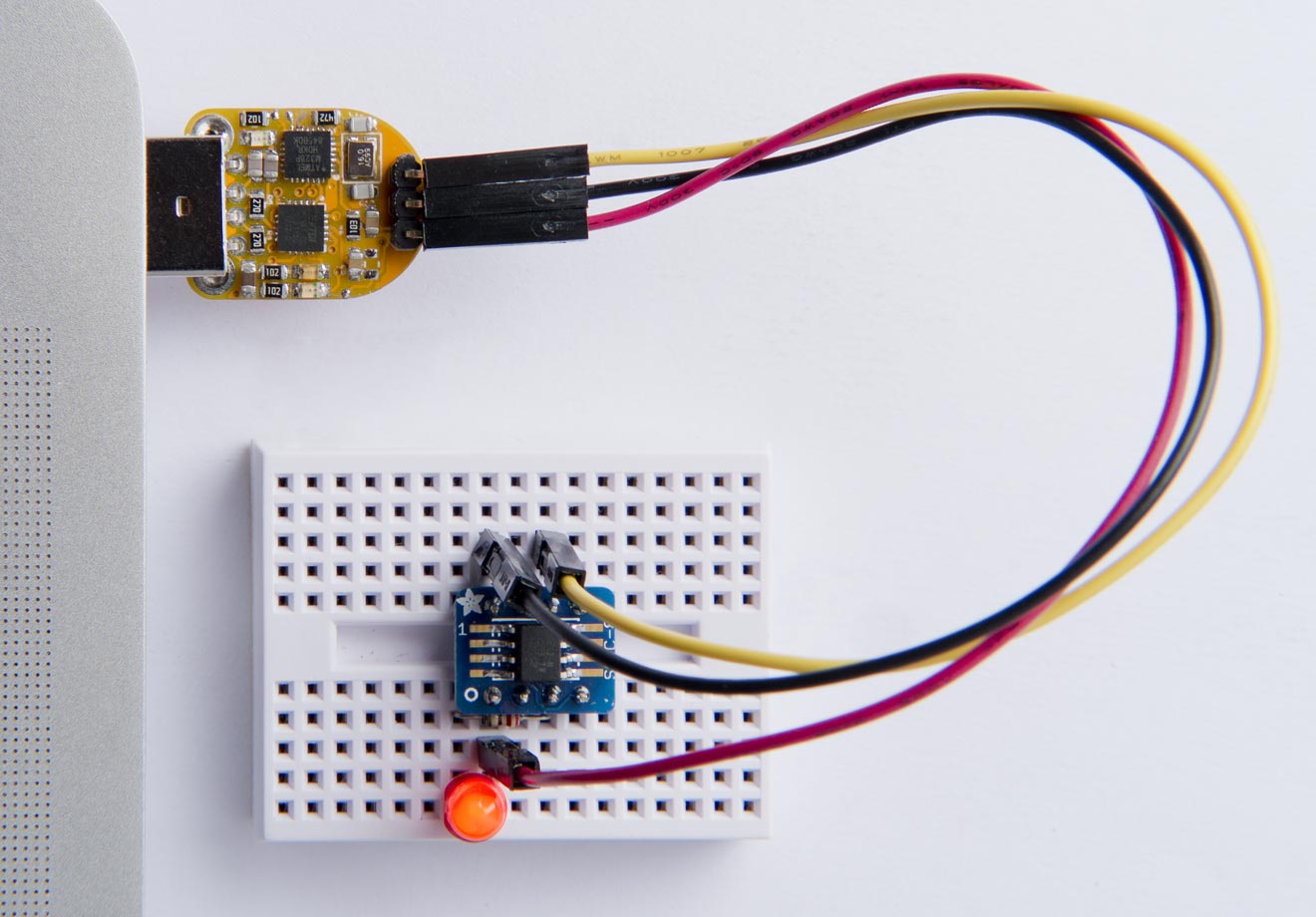
The connection is quite straightforward but the pin-pin connection between the Programmer and the Attiny is illustrated below to prevent mistakes:
Programmer – Attiny
GND – GND
5V – VCC
UPDI – UPDI
2. With the microcontroller connected to your Arduino UPDI programmer, we are now ready to upload code to the ATtiny.
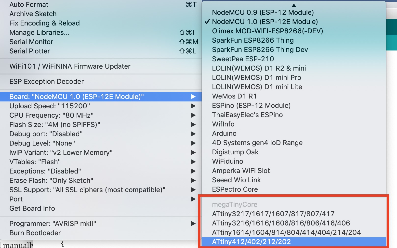
3. Open or write the code you would like to upload. Verify the code to ensure that there is no error, then go to Tools -> Board, and scroll down till you see the ATtiny you are working with on the list and select it. The ATtiny boards will be automatically installed after you install the megaTinyCore.
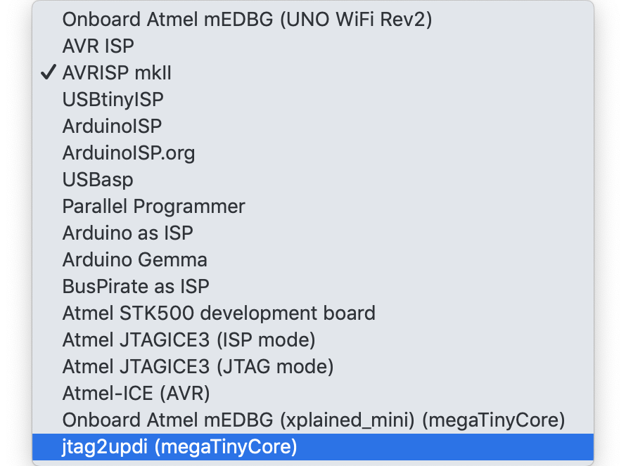
4. This should update the parameters being displayed when you click tools. Now we need to tell the Arduino IDE to use our programmer. To do this, go to Tools->Programmers (towards the end). Scroll down on the pane and select jtag2updi (megaTinycore) as your programmer.
5. With that done, your screen should now look like the image below when you click on tools;
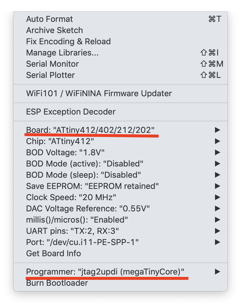
6. This means all lights are green. Now select the port to which the Programmer Stick is connected and hit the upload button on the IDE. You should immediately see the upload process and when complete, the microcontroller should perform as programmed.
There you go! Compared to the former ATtiny microcontrollers, these new series of MCUs come with higher amount of flash memories, cost a whole lot less and are all-around more efficient compared to the previous set as such they should probably be considered when next you are making the choice of a tiny low-cost, low-power microcontroller for your project and thanks to today’s project, you have a permanent programmer to sort their needs.