

Programmable Bridge Resistive Sensor Signal Conditioner
- Rajkumar Sharma
- 115 Views
- easy
- Tested
- SKU: EL139668
- Quote Now
- 0 Likes

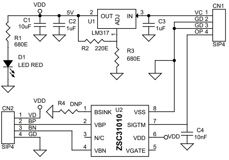
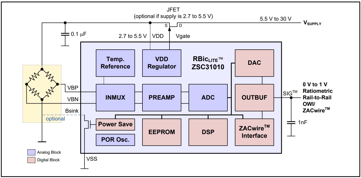
The module presented here is a sensor signal conditioner based on ZSC31010 CMOS integrated circuit, which enables easy and precise calibration of resistive bridge sensors via EEPROM programming. When mated to a resistive bridge sensor, it will digitally calibrate offset and gain with the option to calibrate offset and gain coefficients and linearity over temperature. A second-order compensation can be enabled for temperature coefficients of gain or offset or bridge linearity. ZSC31010 module communicates via IDT’s ZACwire serial interface to the host computer and it is easily mass-calibrated in a Windows environment. Once calibrated, the output signal pin can provide selectable 0 to 1 V absolute analog output; rail-to-rail ratiometric analog output; or digital serial output of bridge data with optional temperature data. U1 LM317 provides the 5V DC to the sensor chip. D1 is the power LED.
Click the link below to download the calibration software, more information about the ZSC31010, and a video tutorial about the ZACwire interface.
Features
- Supply Input 4V DC to 24V DC
- Output 0 to 1V Or Digital
- Current Consumption Approx 6mA Including LED
- Digital compensation of sensor offset, sensitivity, temperature drift, and non-linearity
- Accommodates differential sensor signal spans, from 3 mV/V to 105 mV/V
- ZACwire™ One-Wire Interface (OWI)
- Internal temperature compensation and detection via bandgap PTAT (proportional to absolute temperature)
- Output options: rail-to-rail analog output voltage, absolute analog voltage, digital ZACwire™ One Wire Interface (OWI)
- Optional sequential output of both temperature and bridge readings on ZACwire™ digital output
- Fast response time, 1 ms (typical)
- Chopper-stabilized true differential ADC
- Buffered and chopper-stabilized output DAC
- PCB Dimensions 22.54 x 18.10 mm
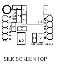
Connections and Other Details
- CN1: Pin 1 = VCC 4V to 24V DC, Pin 2,3 = GND, Pin 4 = Output Analog/Digtal ZACwire Interface
- CN2: Bridge Sensor Pin1 = VDD, Pin 3 = VBP, Pin 4 = VBN
- D1: Power LED
Schematic
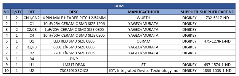
Parts List
| NO | QNTY | REF | DESC | MANUFACTURER | SUPPLIER | SUPPLIER PART NO |
|---|---|---|---|---|---|---|
| 1 | 2 | CN1,CN2 | 4 PIN MALE HEADER PITCH 2.54MM | WURTH | DIGIKEY | 732-5317-ND |
| 2 | 1 | C1 | 10uF/25V CERAMIC SMD SIZE 1206 | YAGEO/MURATA | DIGIKEY | |
| 3 | 2 | C2,C3 | 1uF/25V CERAMIC SMD SIZE 0805 | YAGEO/MURATA | DIGIKEY | |
| 4 | 1 | C4 | 10nF/50V CERAMIC SMD SIZE 0805 | YAGEO/MURATA | DIGIKEY | |
| 5 | 1 | D1 | LED RED SMD SIZE 0805 | OSRAM | DIGIKEY | 475-1278-1-ND |
| 6 | 2 | R1,R3 | 680E 1% SMD SIZE 0805 | YAGEO/MURATA | DIGIKEY | |
| 7 | 1 | R2 | 220E 1% SMD SIZE 0805 | YAGEO/MURATA | DIGIKEY | |
| 8 | 1 | R4 | DNP | |||
| 9 | 1 | U1 | LM317 DPAK | ST | DIGIKEY | 497-1574-1-ND |
| 10 | 1 | U2 | ZSC31010 SOIC8 | IDT, Integrated Device Technology Inc | DIGIKEY | 1833-1003-1-ND |
Connections
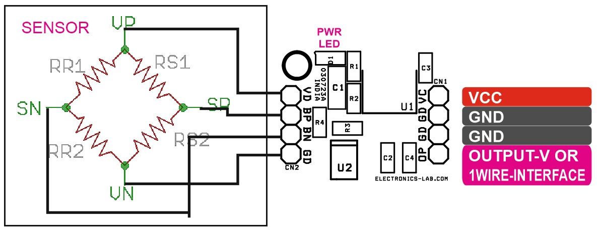
Application Diagram
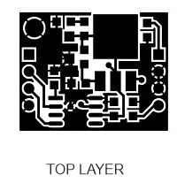
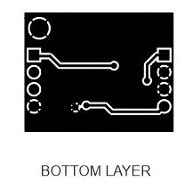
Gerber View
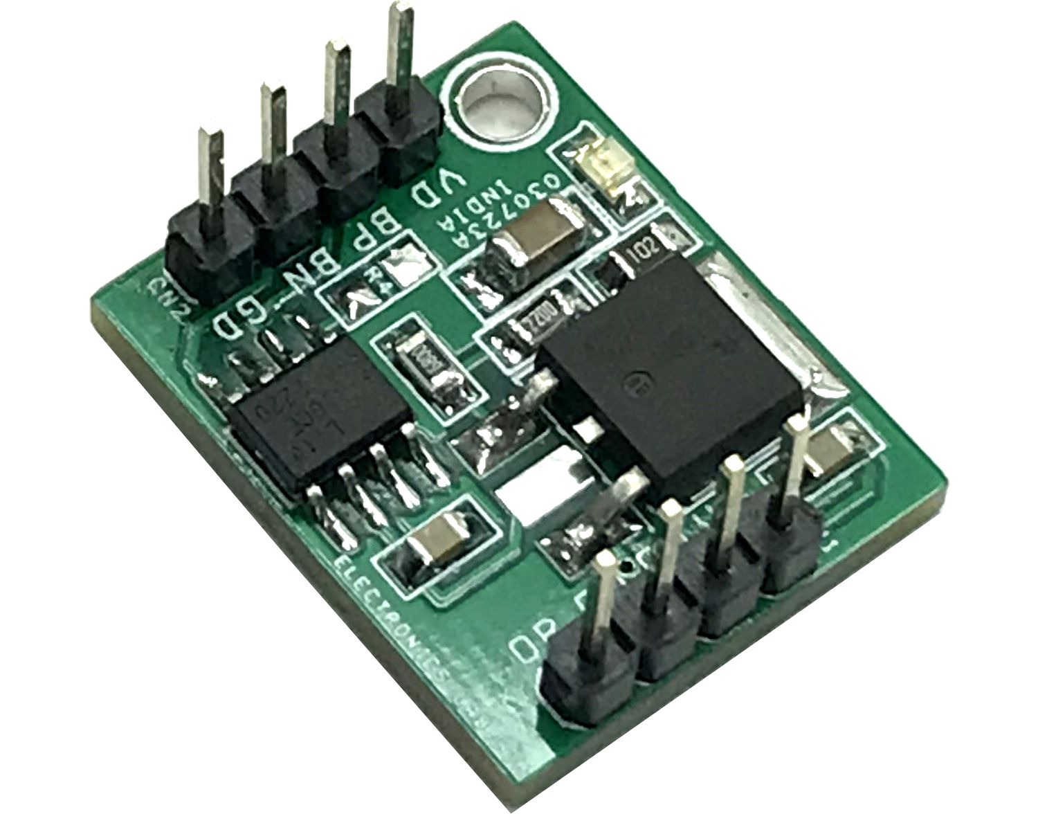
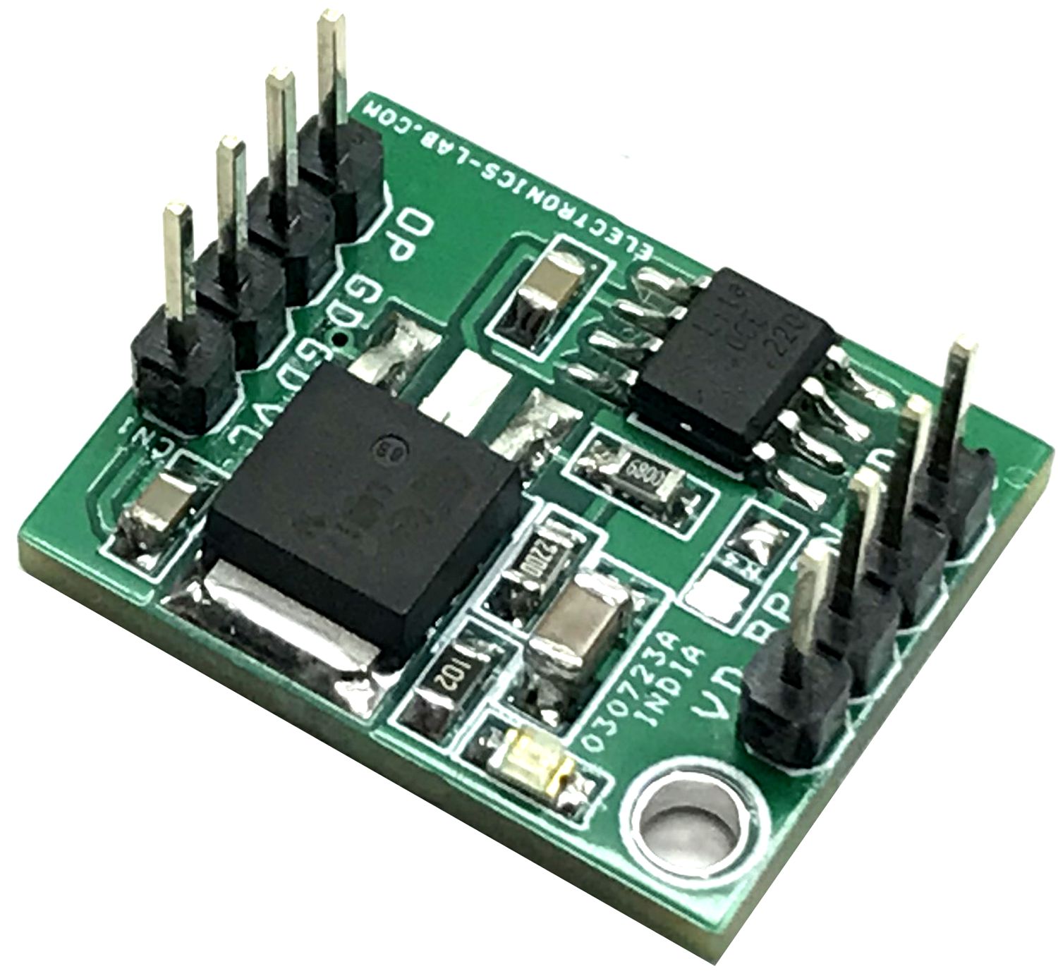
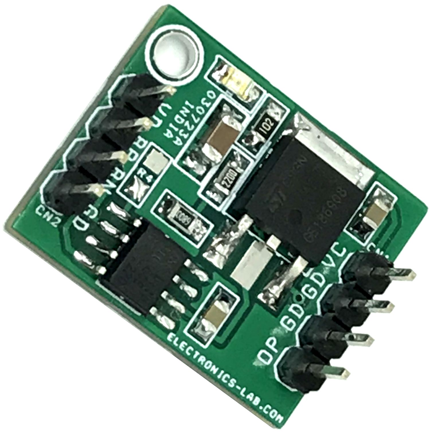
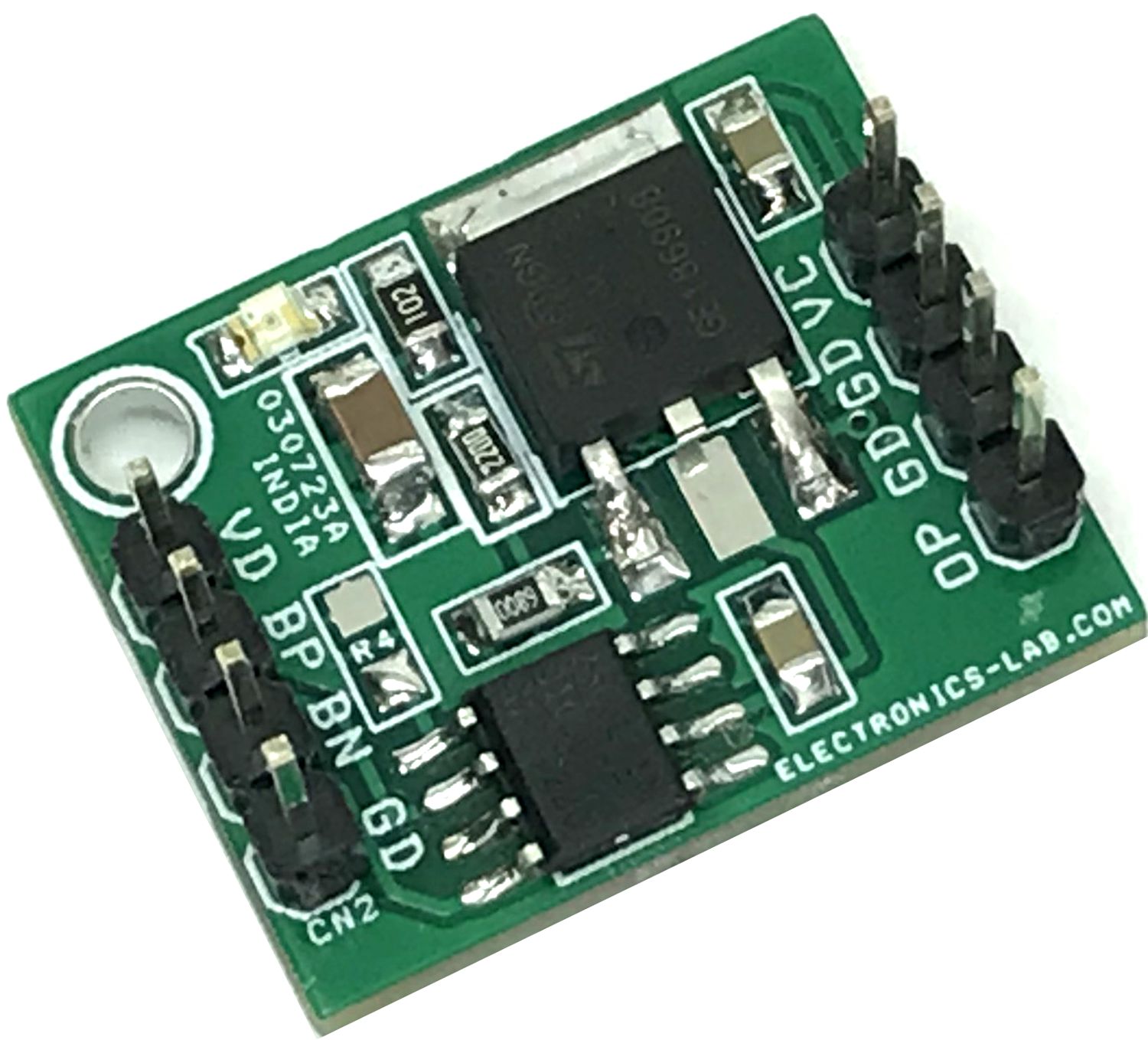
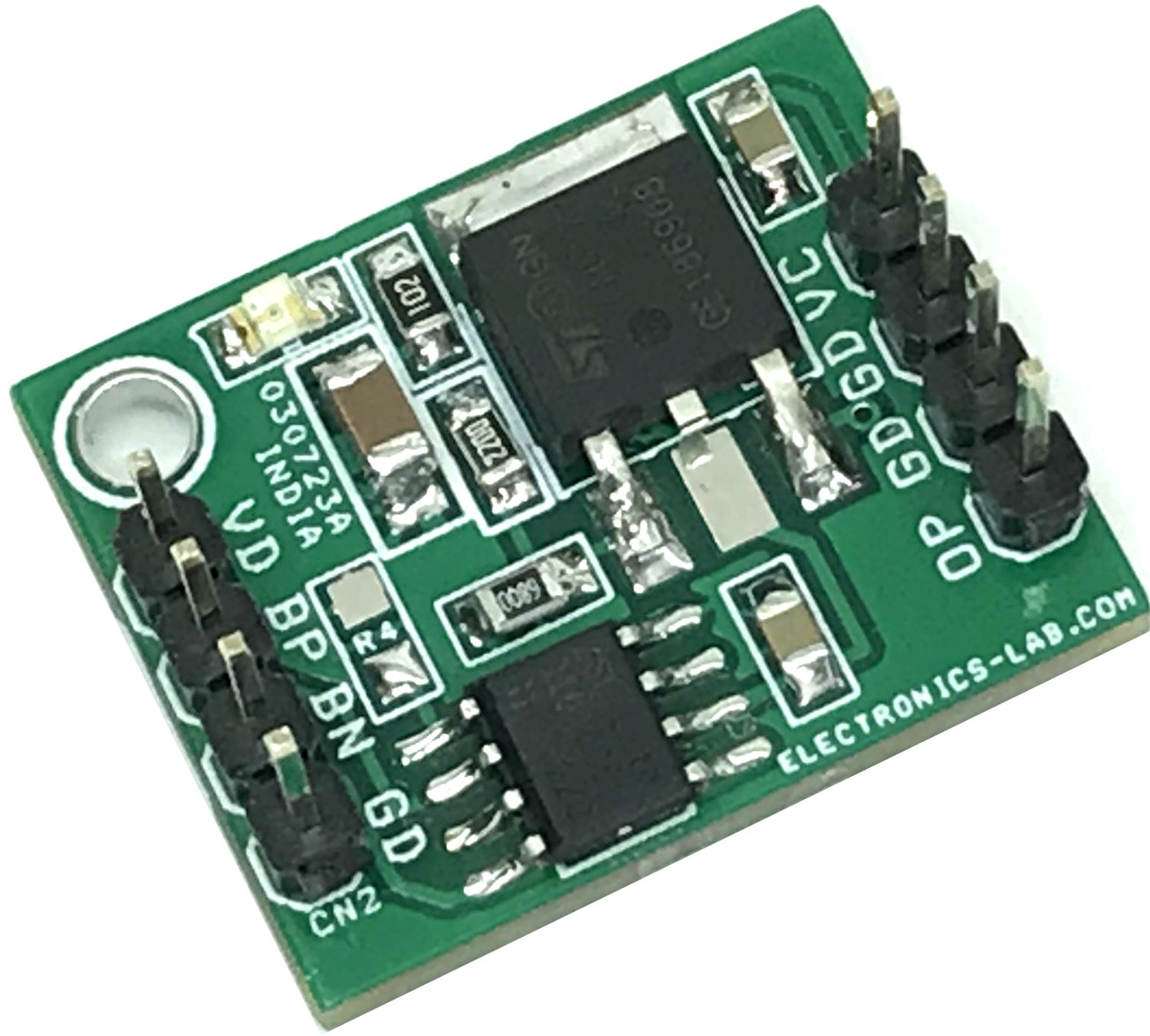
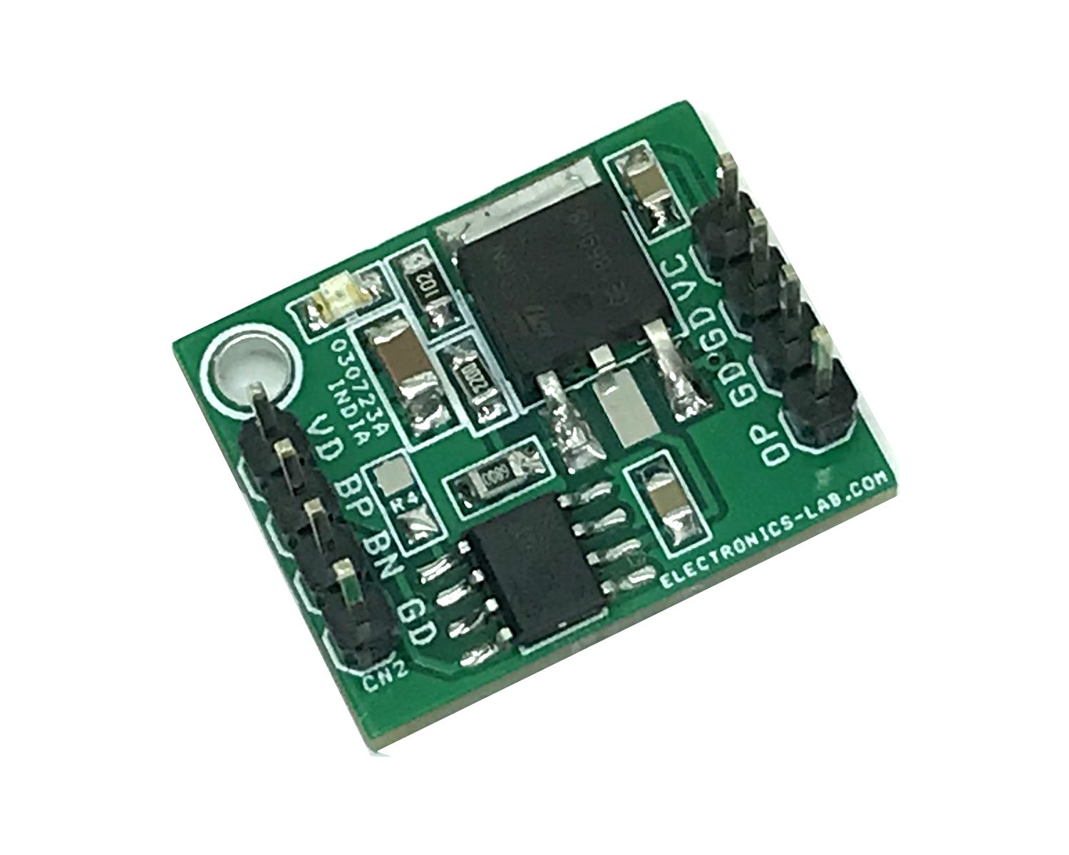
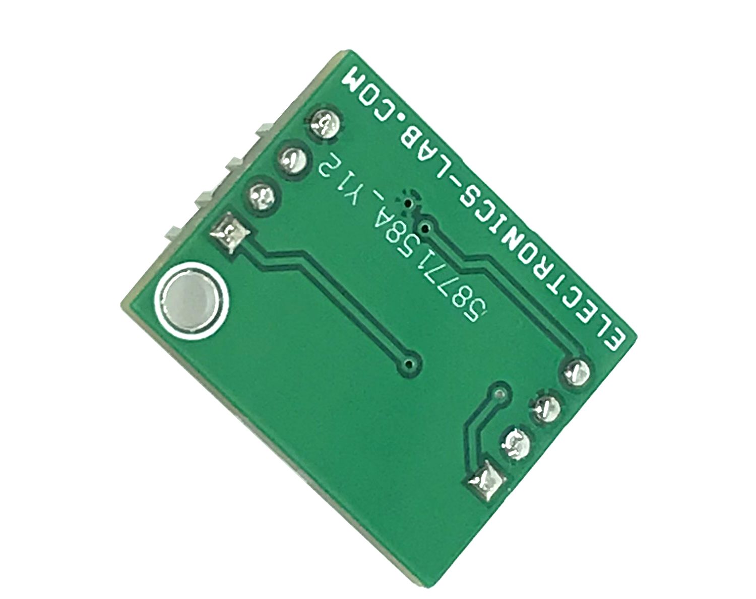
Photos
ZSC31010 Datasheet
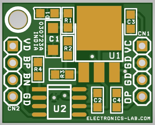
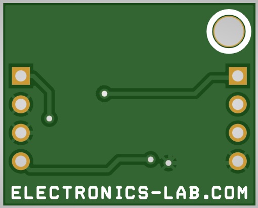
PCB


 Converter")
 to Single-Supply Signal Converter for ADC")