
Single Channel PS3 Wireless Remote ON/OFF Switch
- Rajkumar Sharma
- 102 Views
- easy
- Tested
- SKU: EL140686
- Quote Now
- 0 Likes

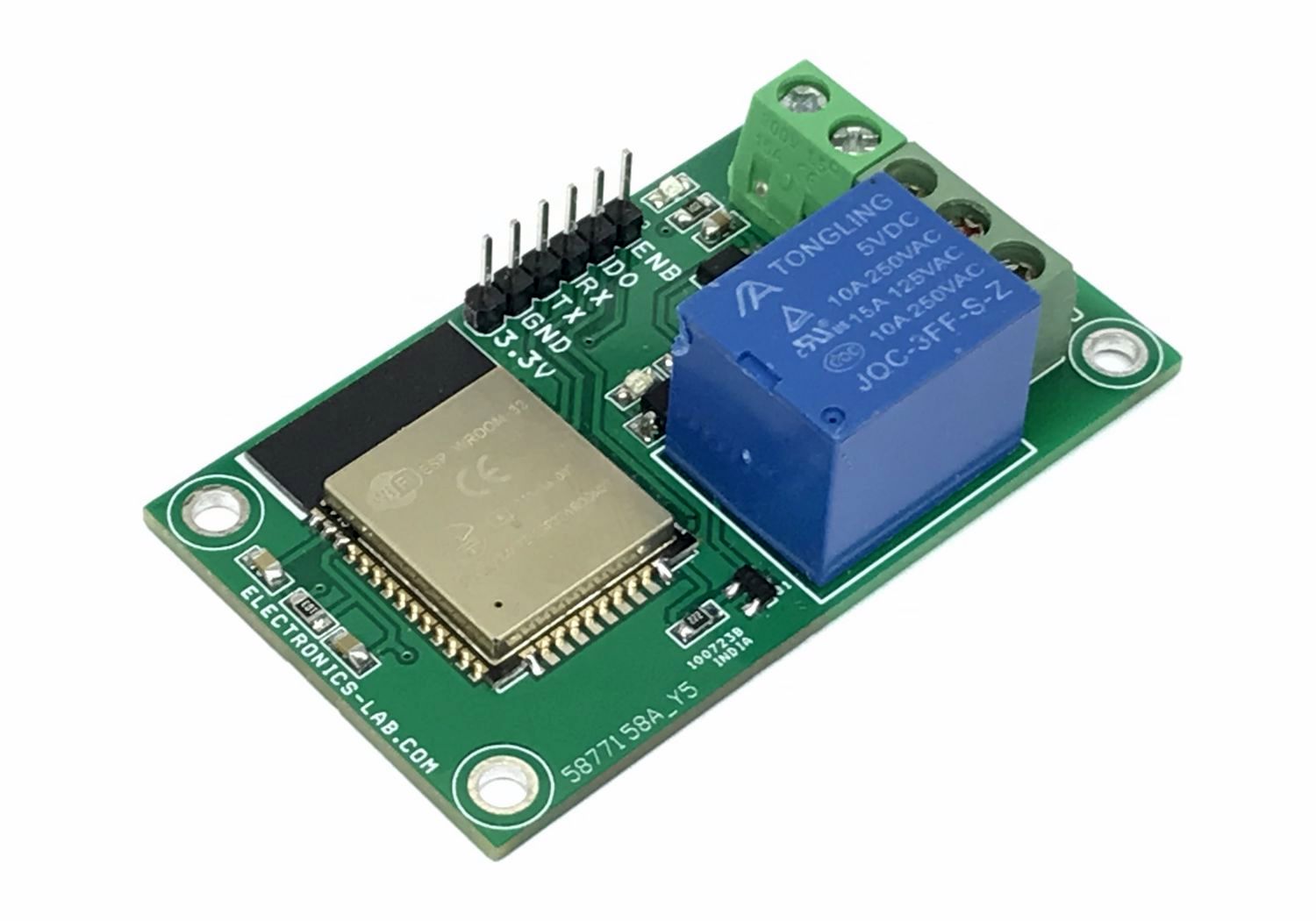
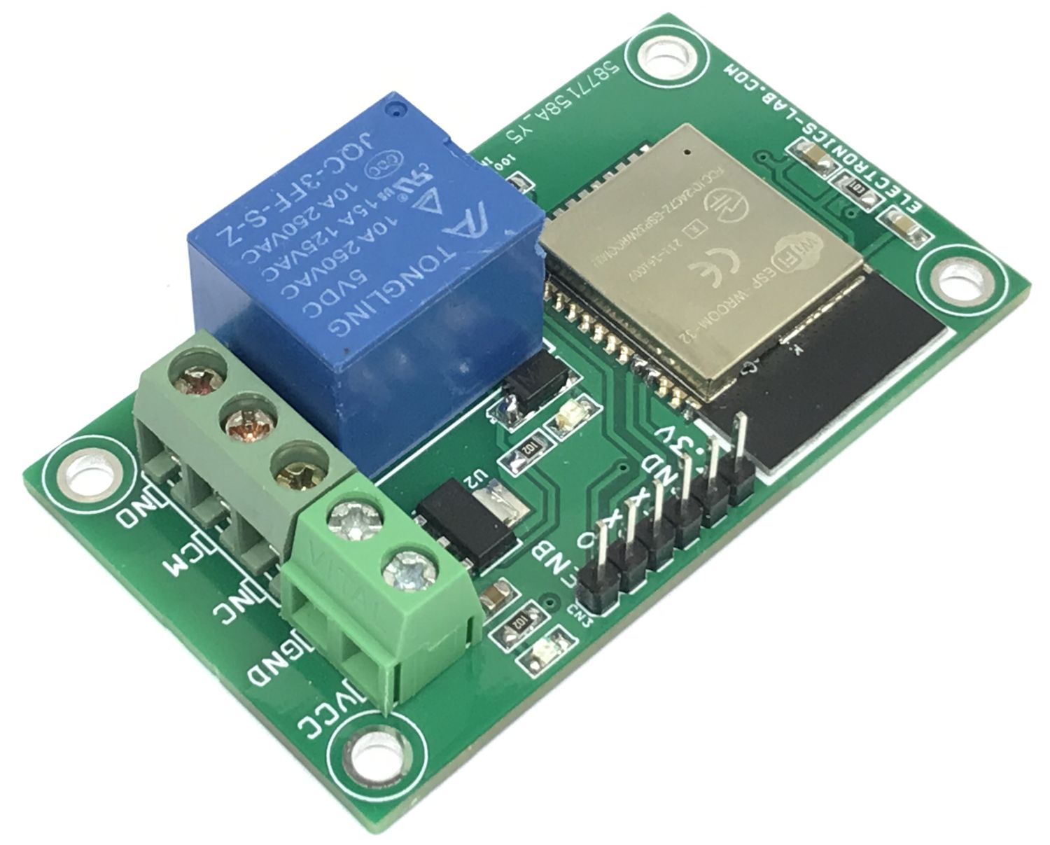
The board presented here is multipurpose hardware which includes the ESP32-Wroom module, 3.3V regulator, 5V relay, Power LED, Relay LED, and connector to program the ESP-32 Module. The project requires 5VDC and consumes 60mA current when the relay is ON. The project can be used in IoT applications and the relay can be controlled using Bluetooth or WiFi. The hardware helps users develop single-channel relay-based projects. The relay can be controlled over Wi-Fi, and Bluetooth wireless communication using appropriate code. The relay is connected to the GPIO4 pin of the ESP32 module.
Features
- Supply 5VDC
- Load Current 60mA (When Relay is ON)
- Relay Contacts Normally Open and Normally Closed
- Relay Contacts Load Current Up to 10A
- On Board Power LED
- On Board Function LED
- Screw Terminal for Power Supply Input
- Screw Terminal for Relay Contacts
- On Board Connector to Upload the Code
- PCB Dimensions 62.87 x 36.20mm
- 4 x 3mm Mounting Holes
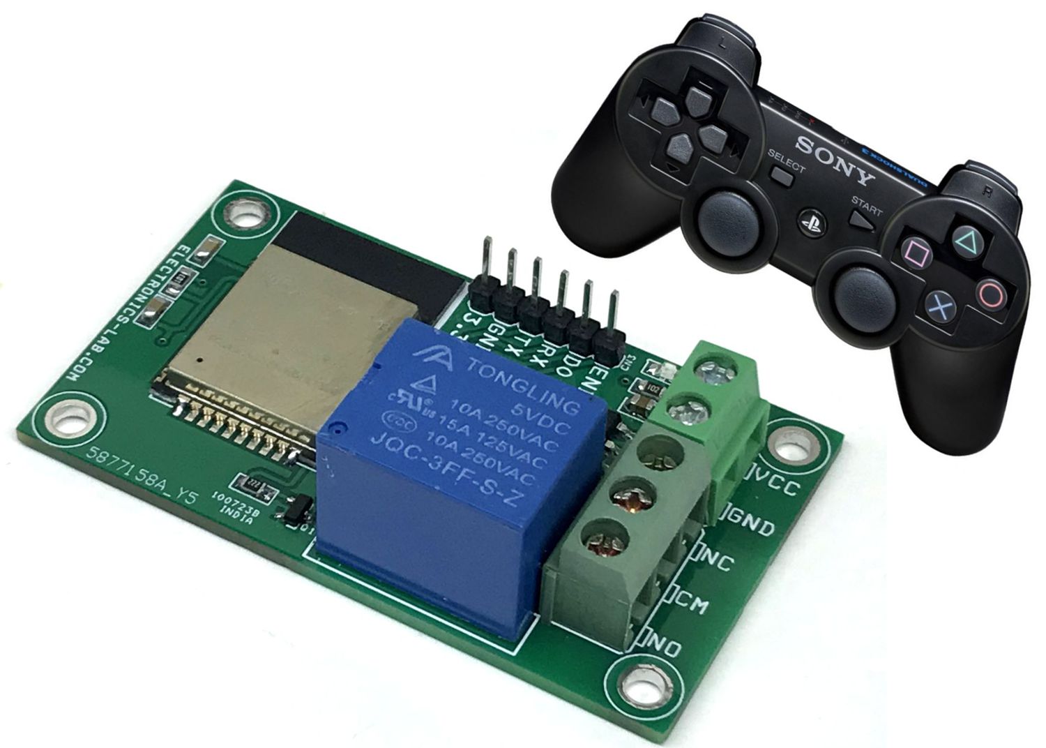
Relay ON/OFF switch using PS3 Wireless Remote
We have tested a simple on/off switch using this hardware and a PS3 wireless remote controller. The PS3 wireless remote works with Bluetooth thus it is easy to pair this board with PS3. Example code is available as a download. This code can be uploaded using Arduino IDE, follow the links below for more info about pairing the PS3 remote, and ESP32 programming.
Code Credits: This is modified code. The original author of the code is DroneWorkShop: https://dronebotworkshop.com/ps3-esp32/
Programming ESP-32 / ESP32S with USB – TTL / UART and Integration with Arduino IDE
- https://mischianti.org/2021/05/30/esp32-wroom-32-esp32-s-flash-pinout-specs-and-ide-configuration-1/
- https://www.studiopieters.nl/esp32-program-a-esp32/
- https://www.14core.com/wiring-and-flashing-programming-esp-32-esp32s-with-usb-ttl-uart/
- https://techtutorialsx.com/2017/06/05/esp-wroom-32-uploading-a-program-with-arduino-ide/
Getting Started with ESP32
Pairing PS3 Remote with ESP32 Module
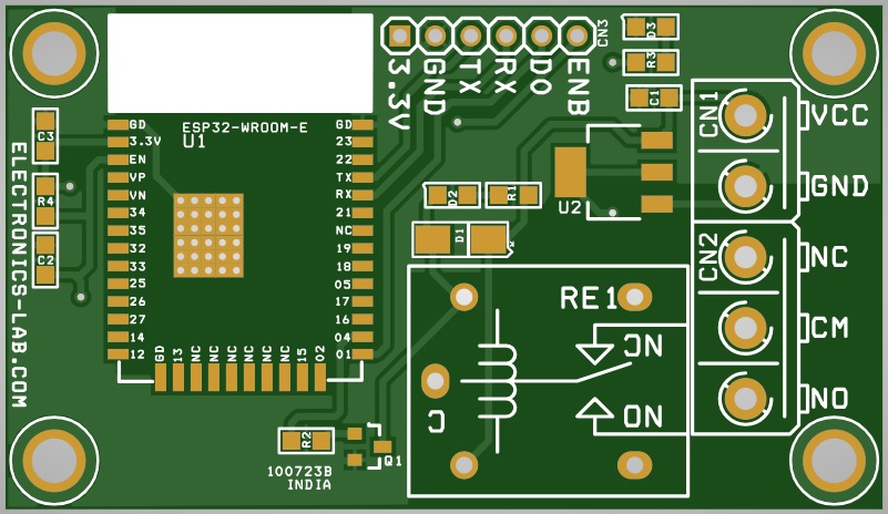
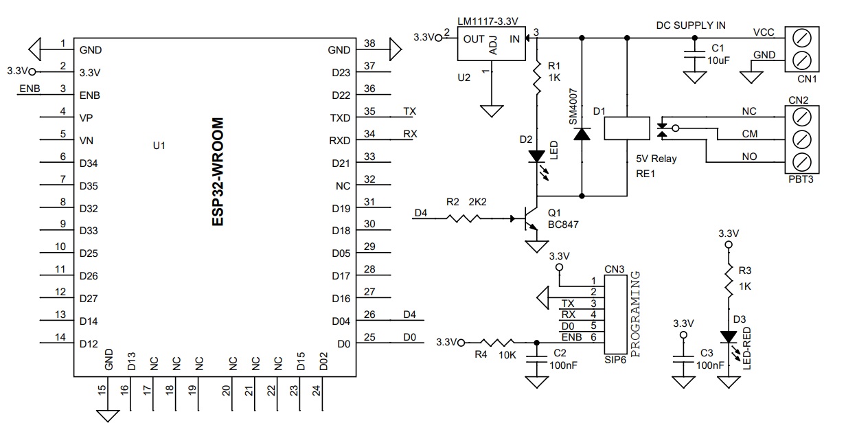
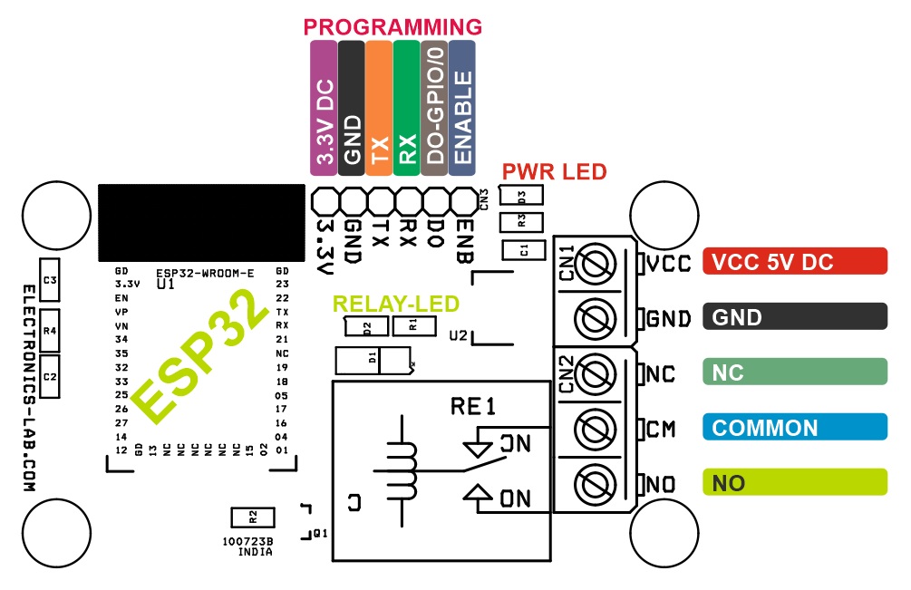
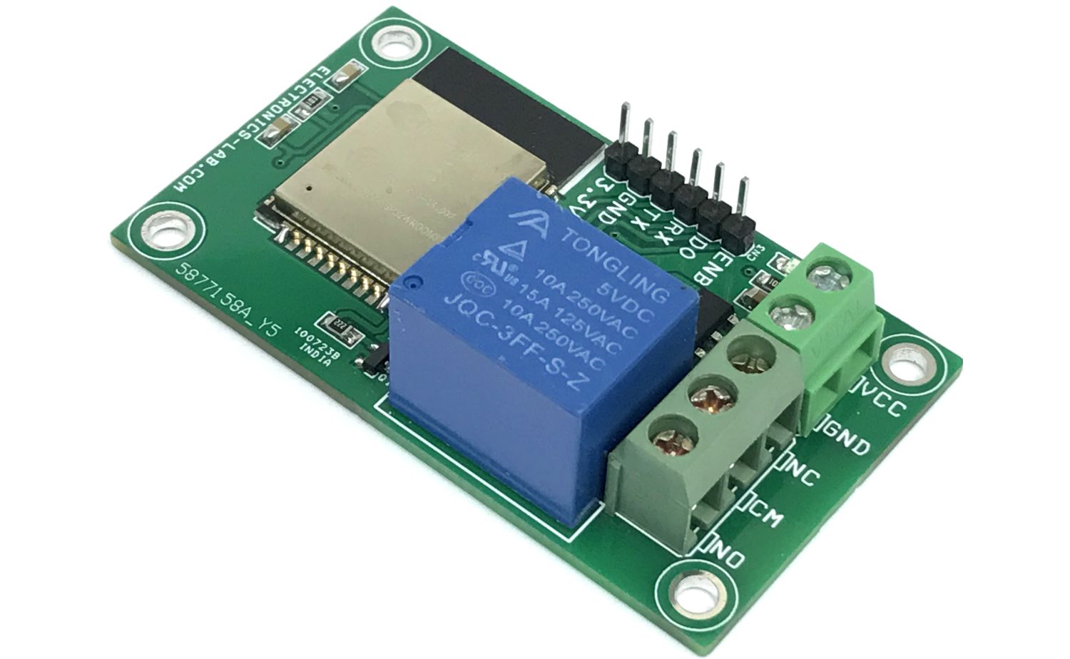
Connections Description
- CN1 Power Supply: Pin 1 = VCC 5V DC, Pin 2 = GND
- CN2 Relay Contacts: Pin 1 = Normally Open, Pin 2 = Common, Pin 3 = Normally Closed (Relay Contacts)
- CN3 Programming Connector: Pin 1 = 3.3V, Pin 2 = GND, Pin 3 = TX, Pin 4 = RX, Pin 5 = GPIO-0 (DO) , Pin 6 = Enable
- D1: Power LED
- D2: Relay LED
- Relay: ESP32 -> GPIO4
Schematic
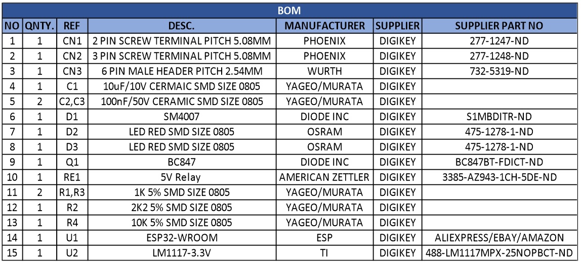
Parts List
| NO | QNTY. | REF | DESC. | MANUFACTURER | SUPPLIER | SUPPLIER PART NO |
|---|---|---|---|---|---|---|
| 1 | 1 | CN1 | 2 PIN SCREW TERMINAL PITCH 5.08MM | PHOENIX | DIGIKEY | 277-1247-ND |
| 2 | 1 | CN2 | 3 PIN SCREW TERMINAL PITCH 5.08MM | PHOENIX | DIGIKEY | 277-1248-ND |
| 3 | 1 | CN3 | 6 PIN MALE HEADER PITCH 2.54MM | WURTH | DIGIKEY | 732-5319-ND |
| 4 | 1 | C1 | 10uF/10V CERMAIC SMD SIZE 0805 | YAGEO/MURATA | DIGIKEY | |
| 5 | 2 | C2,C3 | 100nF/50V CERAMIC SMD SIZE 0805 | YAGEO/MURATA | DIGIKEY | |
| 6 | 1 | D1 | SM4007 | DIODE INC | DIGIKEY | S1MBDITR-ND |
| 7 | 1 | D2 | LED RED SMD SIZE 0805 | OSRAM | DIGIKEY | 475-1278-1-ND |
| 8 | 1 | D3 | LED RED SMD SIZE 0805 | OSRAM | DIGIKEY | 475-1278-1-ND |
| 9 | 1 | Q1 | BC847 | DIODE INC | DIGIKEY | BC847BT-FDICT-ND |
| 10 | 1 | RE1 | 5V Relay | AMERICAN ZETTLER | DIGIKEY | 3385-AZ943-1CH-5DE-ND |
| 11 | 2 | R1,R3 | 1K 5% SMD SIZE 0805 | YAGEO/MURATA | DIGIKEY | |
| 12 | 1 | R2 | 2K2 5% SMD SIZE 0805 | YAGEO/MURATA | DIGIKEY | |
| 13 | 1 | R4 | 10K 5% SMD SIZE 0805 | YAGEO/MURATA | DIGIKEY | |
| 14 | 1 | U1 | ESP32-WROOM | ESP | DIGIKEY | ALIEXPRESS/EBAY/AMAZON |
| 15 | 1 | U2 | LM1117-3.3V | TI | DIGIKEY | 488-LM1117MPX-25NOPBCT-ND |
Connections
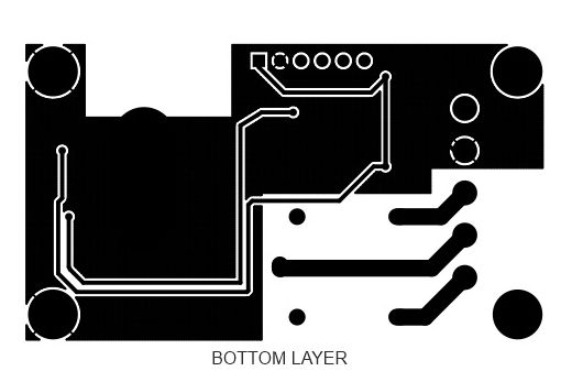
Gerber View
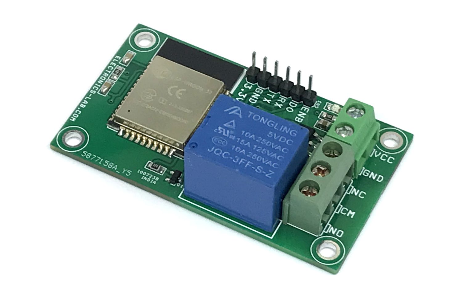
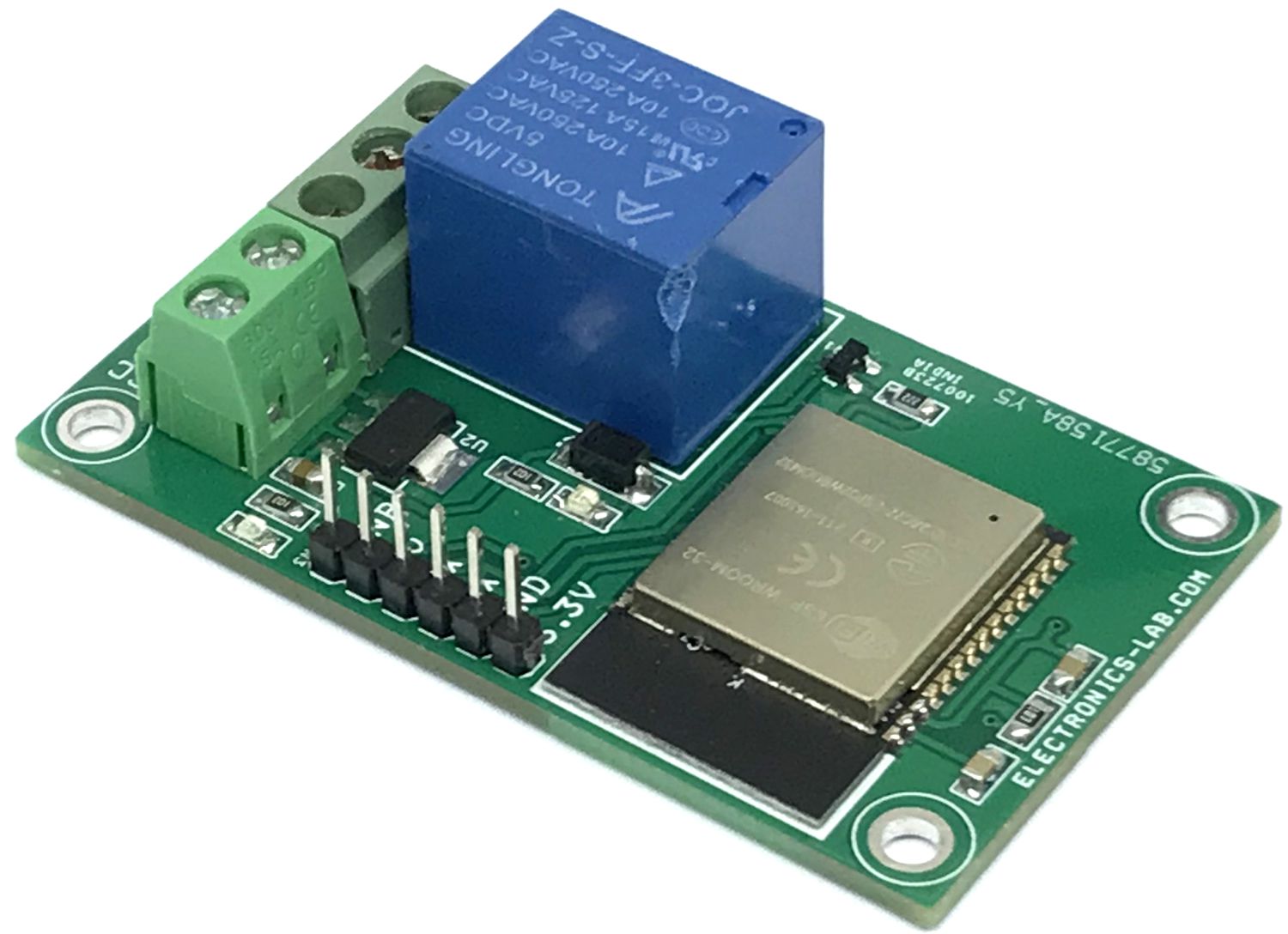
Photos
Video
ESP32-Wroom Datasheet
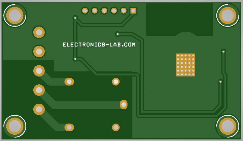
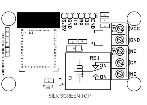
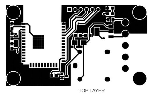
PCB