

USB Single Cell LiPoly Charger
- Rodrigo Forrequi
- http://rusticengineering.wordpress.com
- lubiana@gmail.com
- 21.091 Views
- easy
- Non tested
- 0 Likes

Introduction
Lithium Polymer Batteries are a very common source of power today. Many electronics gadgets have one inside, and they have some reasonable features. I’ve bought great batteries, with different sizes and capacities for my electronics projects. So long I’m using this batteries, coming the problem: charge them.
Charger Version 1
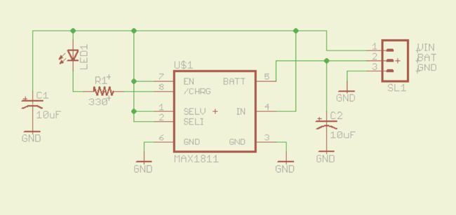
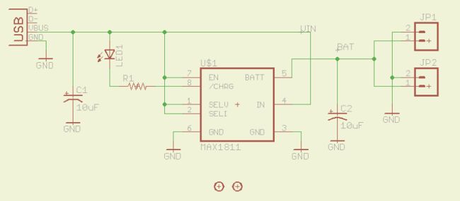
So, we start to find the correct circuit for my DIY charger. After some Google research I found the Maxim MAX1811 IC. It’s a single-cell Lithium battery charger that can be powered directly from a USB or from an external supply up to 6.5V. It’s use a SO-8 Package, easy to solder and can be sampled at Maxim. Other chip features are:
You can select between 4.1V and 4.2V battery regulation point;
You can select between 100mA and 500mA current drain from USB;
There’s a open drain pin (pin_8) for signaling end of charge condition (2.5V < VBATT < BATT Regulation Voltage);
A internal thermal loop limits the MAX1811 die temperature to +135°C by reducing the charging current as necessary.
According to datasheet, MAX1811 is specifically made for USB devices. The minimum voltage to a common USB-powered device may be as low as 4.35V when cable and connector drops are considered. The MAX1811 is optimized for operation at these low input voltage levels. But USB hubs may also provide as much as 5.5V!. At high input voltages (5.5V) and low cell voltages (2.7V), the MAX1811’s thermal loop may limit the charge current until the cell voltage rises.
My design uses 500mA was charging current (pin 2 – SELI – pulled up), but MAX1811 only taken this current if the device is a USB powered source. The other parts are two very common tantalum capacitors and a LED for charging indication. LED is ON on charging state, and OFF when it’s end.
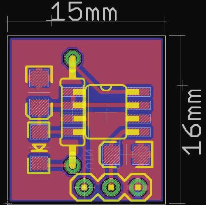
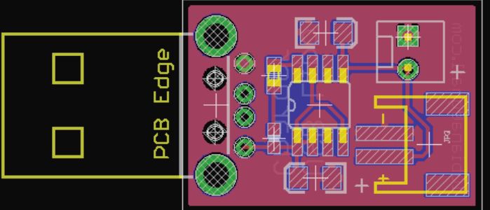
Above you see the schematics and PCB of my version 1:
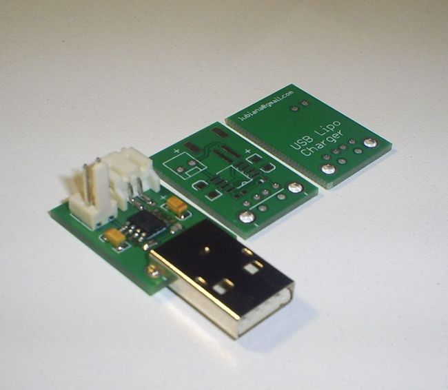
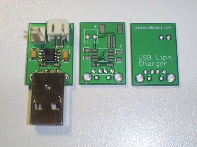
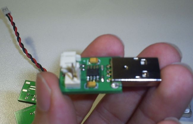
Charger Version 2
Once I’ve finished the version 1 and tested working fine, I look at the board and think Why the hell I can’t put a USB Type A male connector on board?. Well, that’s why there’s some project versions.
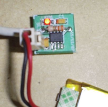
After redesign the circuit, the result was very good, with a new compact board, that now is able to handle batteries with the common JST connector. See the pictures:

Conclusion
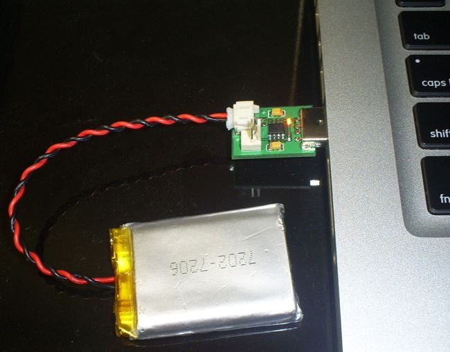
Was a first incursion on LiPo chargers, this project end was success to me. The tests show that MAX1811 is a reliable choice and good alternative over other common choices, like MAX1555 IC.
The thermal loop gives some security to device, so you can connect it to your PC or notebook without fear.
The Eagle files can be downloaded from my blog at http://rusticengineering.wordpress.com. Any question, email me.
PCB


 Batteries")
