Window Comparator – Window Detector with relay output
A window detector circuit, also called window comparator circuit or dual edge limit detector circuit is used to determine whether an unknown input is between two precise reference threshold voltages. It employs two comparators to detect over-voltage or under-voltage condition.
A window detector circuit, also called window comparator circuit or dual edge limit detector circuit is used to determine whether an unknown input is between two precise reference threshold voltages. It employs two comparators to detect over-voltage or under-voltage condition.
This circuit utilizes two comparators in parallel to determine if a signal is between two reference voltages. If the signal is within the window, the output is low thus RELAY is in off condition and also LED is off. Relay provides normally ON and normally OFF switch. If the signal level is outside of the window, the output is high and Relay is in ON condition. For this design, the reference voltages are generated with help of two Trimmer potentiometer. One pot used to set the high voltage level and another one to set the low level voltage adjust. LM358 op-amp used as comparator, it circuit works with 12V DC supply and consumes 50mA current when Relay is in ON state.
Features
- Supply 12V DC
- Two Trimmer Potentiometer Low/High Ref. Adjust
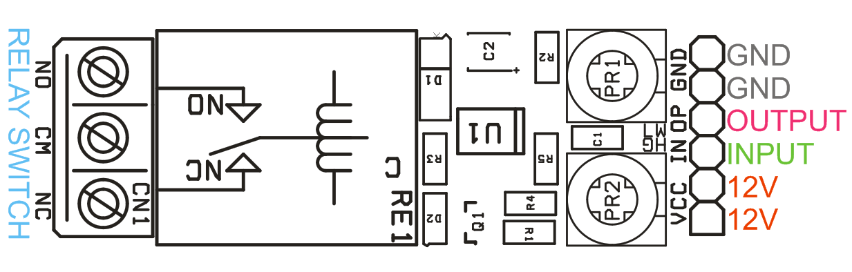
- Relay Switch 230V AC 7 Amps
- Relay Normally Output and Normally Closed Output
- Window Detector Voltage Span 0-12V
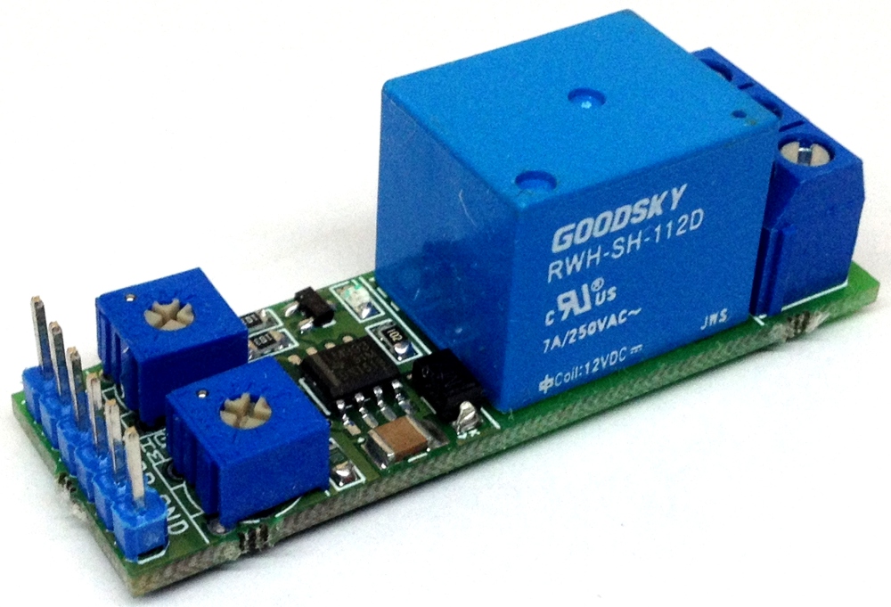
- PCB dimensions: 53.56 x 16.99 mm
Schematic
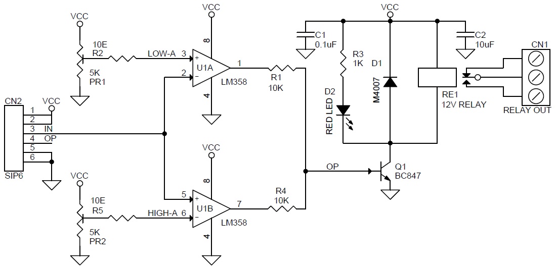
Parts List

Connections
Photos


Hey , how to get exactly oposite functionality? I would like the relay to turn on within the window , not above or below?