Accurate Acoustic Sensor – Sound Frequency to Voltage Converter
The project presented here is a sensitive sound sensor. The circuit converts sound frequency and outputs DC voltage.
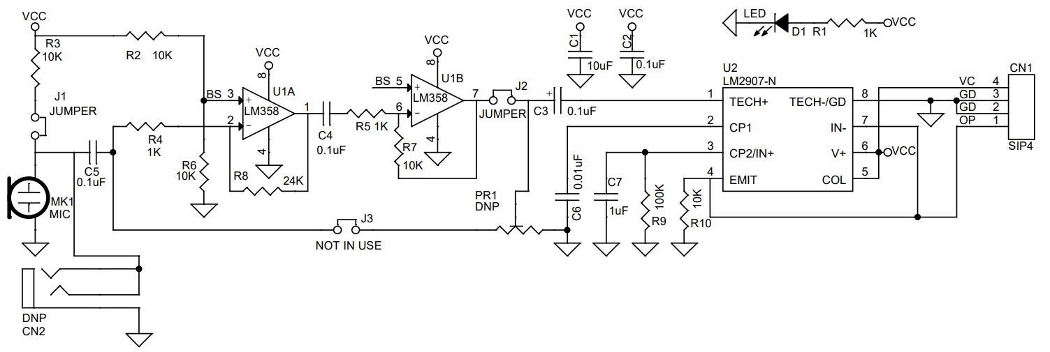
The project presented here is a sensitive sound sensor. The circuit converts sound frequency and outputs DC voltage. The board consists of LM358 OPAMP and LM2907 IC. LM358 is used as a dual-stage microphone preamplifier and LM2907 acts as a frequency to voltage converter. The circuit provides analog voltage output when it detects sound. The output of the sensor is proportional to the audio sound frequency detected through the condenser microphone. The output voltage swings from 3.5V to 10.8V proportional to frequency 330Hz to 933Hz. Output is zero when the sound frequency is below 330Hz. Users may try with other frequency ranges, which can be changed using the following formula, Vo = R9 × C6 × VCC × f. The sensor has better response and accuracy than many sound sensors available on the market. The operating Supply is 12V DC and consumes 20mA current. Jumper J1 and J2 are closed for normal microphone operation.
Optional Direct Audio Signal input
Circuit also has an optional provision to feed a direct audio signal
- Install the following components for direct audio input: CN2 3.5mm EP socket, Jumper J3 (Solder Jumper located under PCB) closed, 10K trimmer Potentiometer to adjust the input audio signal, the input signal should not exceed 28V peak.
- CN2 Stereo Audio Socket Digi Key Part #CP1-3525N-ND, PR1 Trimmer Potentiometer 10K Digi key Part #478-601030-ND
- Do not install the following components for the direct audio signal, J1, J2 Jumper (Solder Jumper Located under PCB) R2, R3, U1, R4, R6, R8, C4, R5, R7.
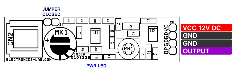
Connections CN1
- CN1 Pin 1 VCC 12V DC Input
- CN1 Pin 2 GND
- CN1 Pin 3 GND
- CN1 Pin 4 DC Voltage Output
- Jumper J1: Closed
- Jumper J2: Closed (Solder Jumper located Under PCB)
- D1 Power LED
- MK1 Condenser Microphone ( Sound Sensor)
Features
- Operating Power Supply 12V DC @ 20mA
- Header Connector for Power input and Signal Output
- Output DC Voltage 3.5V to 10.80V DC
- Frequency Response 330Hz to 933Hz
- On Board Micro-Phone to Detect the Sound
- Optional Direct Audio Input Facility with Input Signal Adjust Trimmer
- Power LED
- PCB Dimensions 56.83 x 15.24mm
Schematic
Parts List
| NO. | QNTY. | REF. | DESC. | MANUFACTURER | SUPPLIER | PART NO |
|---|---|---|---|---|---|---|
| 1 | 1 | CN1 | 4 PIN MALE HEADER CONNECTOR | WURTH | DIGIKEY | 732-5317-ND |
| 2 | 2 | PR1,CN2,J3 | DNP | DO NOT INSTALL | ||
| 3 | 1 | C1 | 10uF/16V SMD SIZE 1206 | YAGEO/MURATA | DIGIKEY | |
| 4 | 4 | C2,C3,C4,C5 | 0.1uF/50V SMD SIZE 0805 | YAGEO/MURATA | DIGIKEY | |
| 5 | 1 | C6 | 0.01uF/25V SMD SIZE 1206 | YAGEO/MURATA | DIGIKEY | |
| 6 | 1 | C7 | 1uF/16V SMD SIZE 1206 | YAGEO/MURATA | DIGIKEY | |
| 7 | 1 | D1 | LED SMD SIZE 0805 | LITE ON INC | DIGIKEY | 160-1427-1-ND |
| 8 | 1 | J1 | JUMPER-2 MALE HEADER PITCH 2.54MM | WURTH | DIGIKEY | 732-5315-ND |
| 9 | 1 | J1 | SHUNT FOR JUMPER J1 | SULLINS CONCT | DIGIKEY | S9001-ND |
| 10 | 1 | MK1 | MIC-CONDENSOR MICROPHONE | PUI AUDIO | DIGIKEY | 668-1484-ND |
| 11 | 3 | R1,R4,R5 | 1K 5% SMD SIZE 0805 | YAGEO/MURATA | DIGIKEY | |
| 12 | 5 | R2,R3,R6,R7,R10 | 10K 5% SMD SIZE 0805 | YAGEO/MURATA | DIGIKEY | |
| 13 | 1 | R8 | 24K 1% -5% SMD SIZE 0805 | YAGEO/MURATA | DIGIKEY | |
| 14 | 1 | R9 | 100K 1% SMD SIZE 0805 | YAGEO/MURATA | DIGIKEY | |
| 15 | 1 | U1 | LM358 SO8 | TI | DIGIKEY | 296-1014-1-ND |
| 16 | 1 | U2 | LM2907-N SO8 | TI | DIGIKEY | LM2907M-8-ND |
Connections
Gerber View
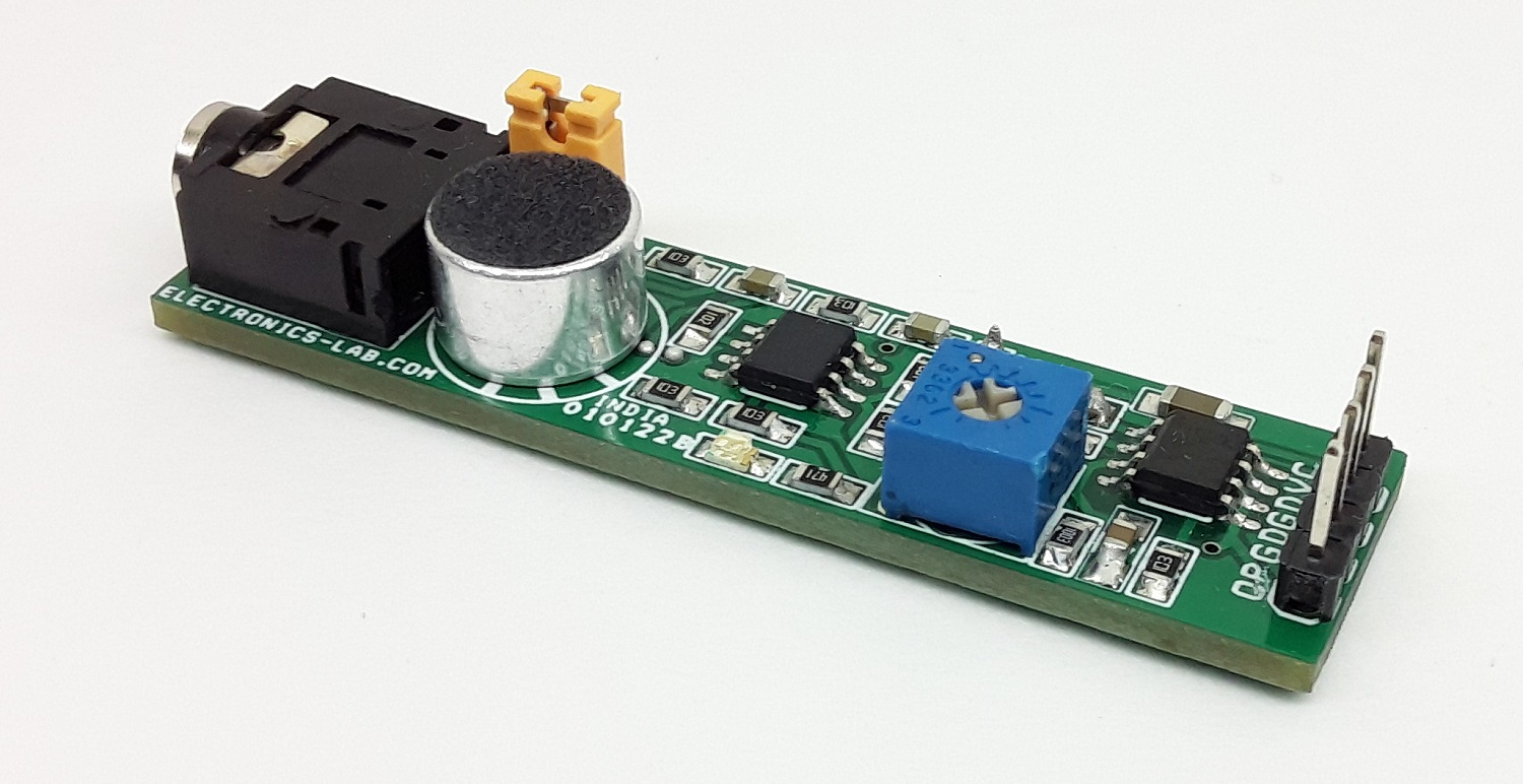
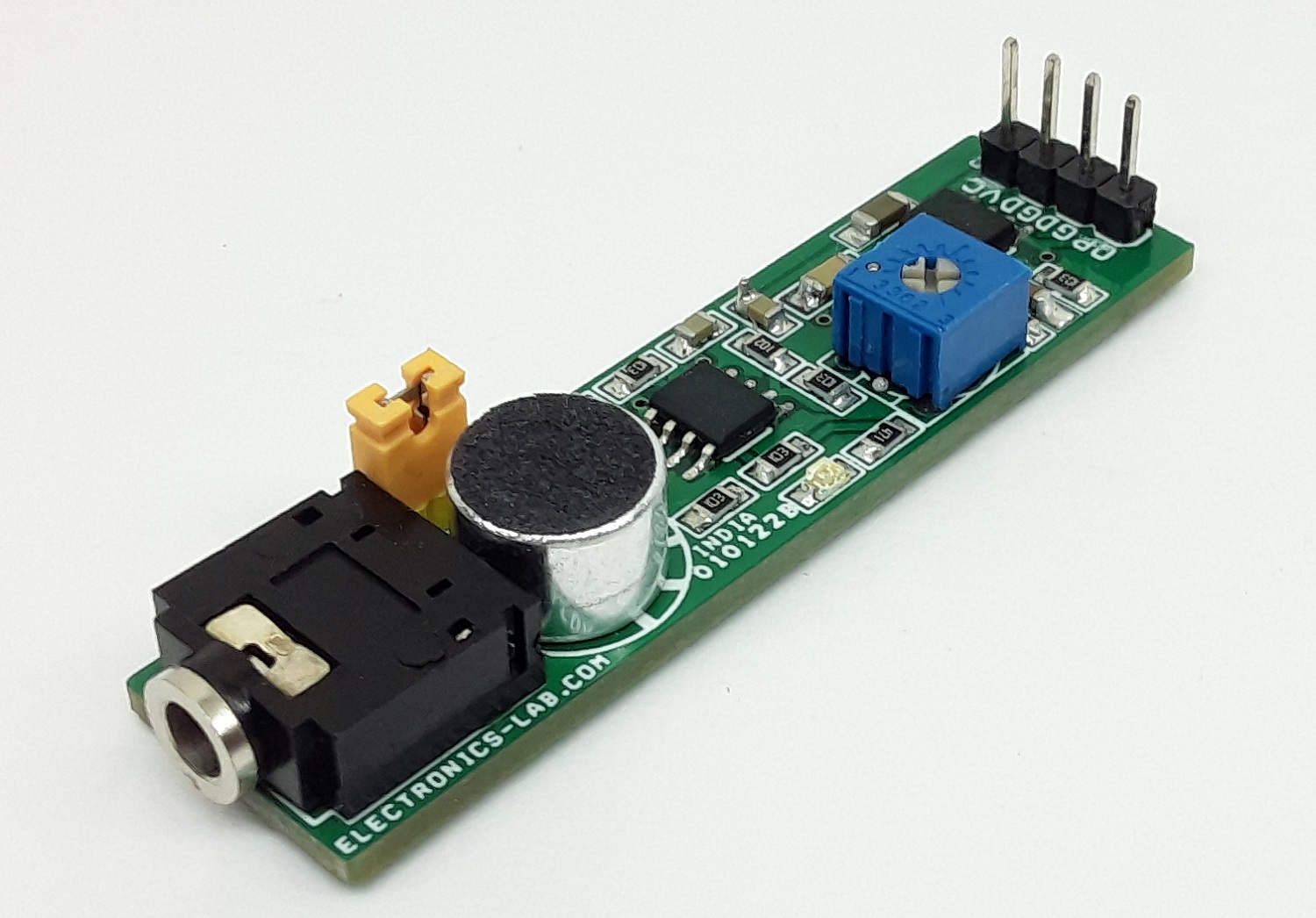
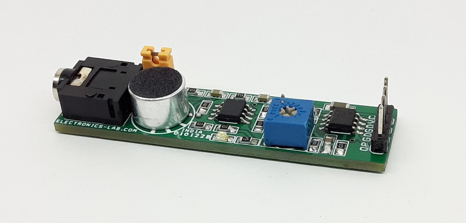
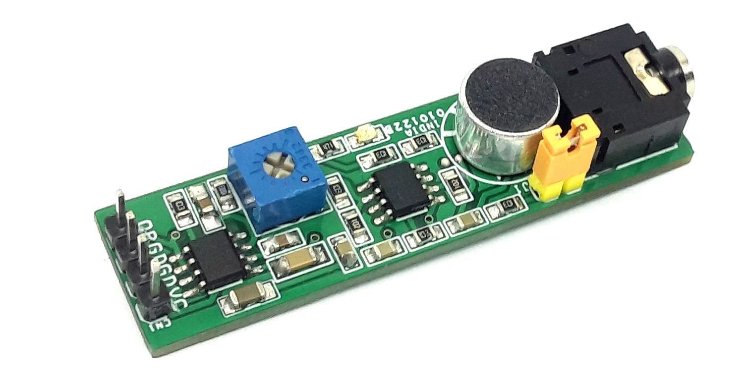
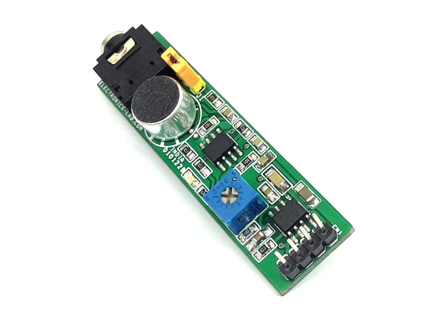
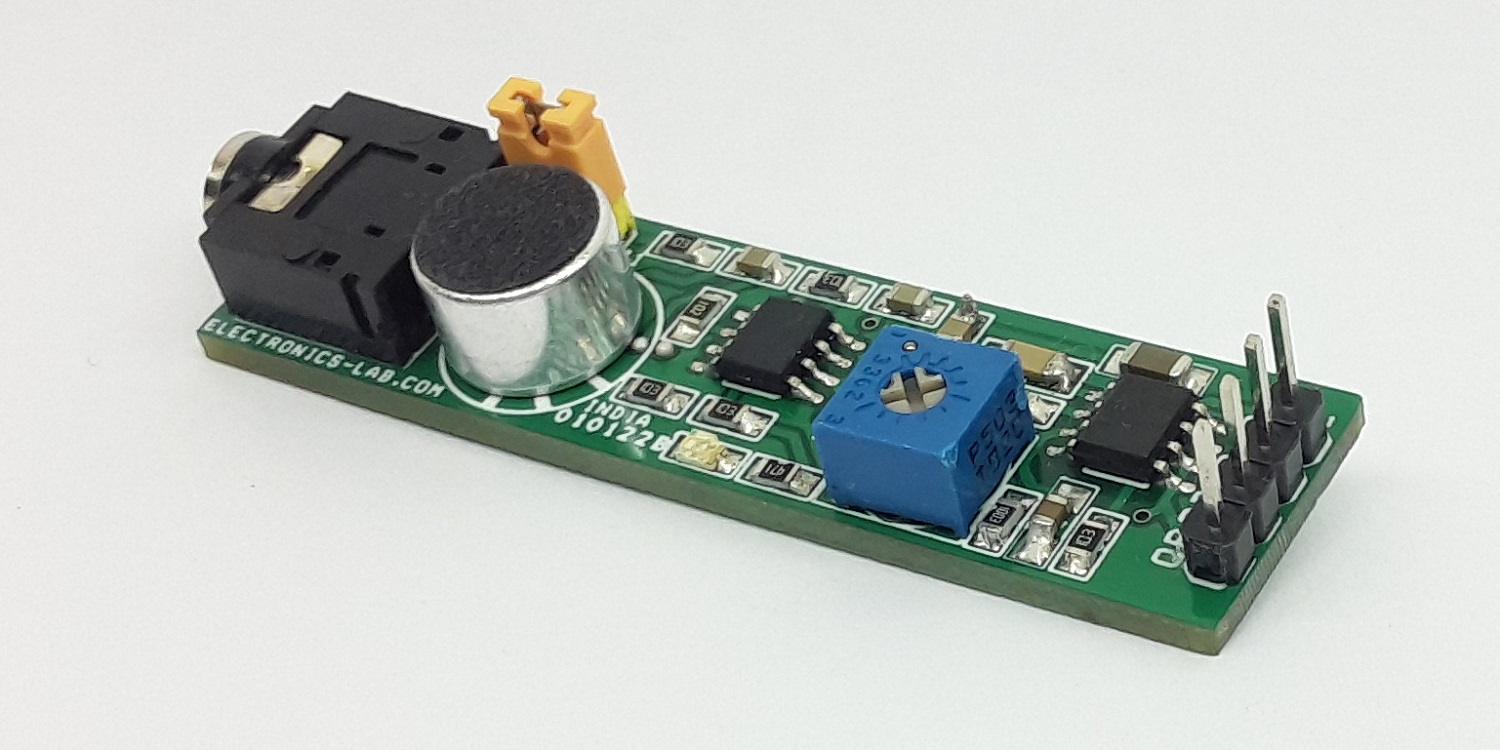
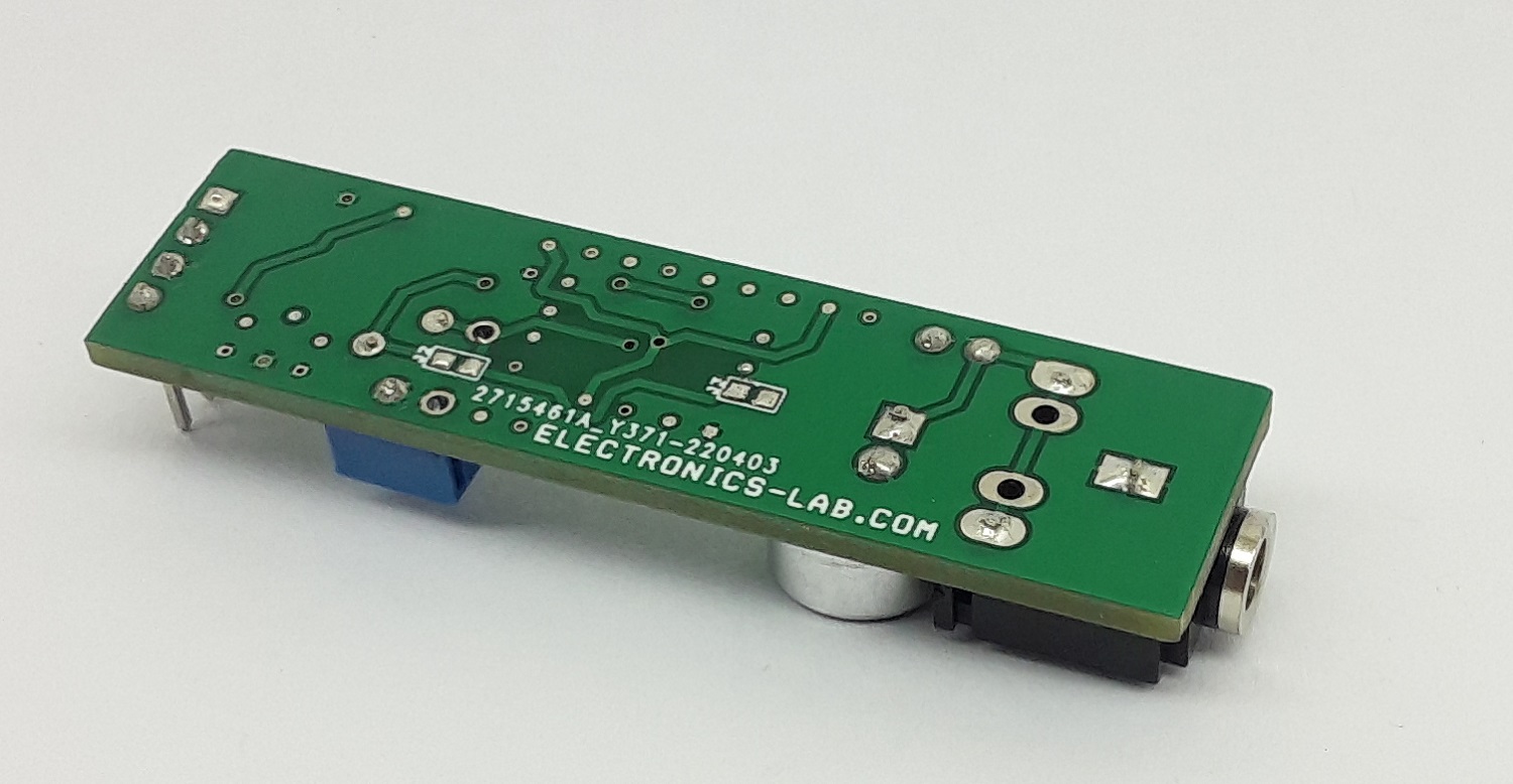
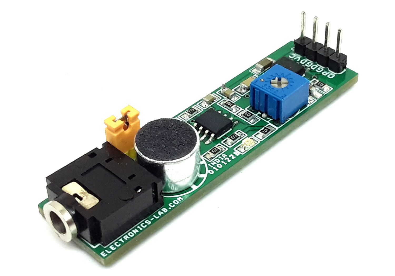
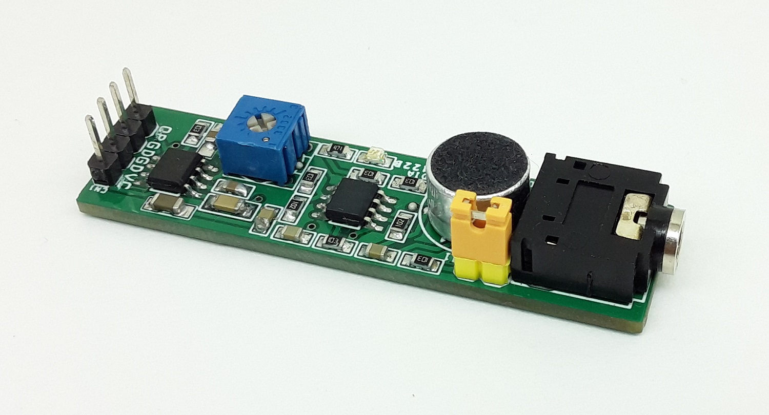
Photos
Video