

4 Channel RC Servo Controller Board
- Rajkumar Sharma
- 14.894 Views
- moderate
- Tested
- SKU: EL49006
- Quote Now
- 0 Likes

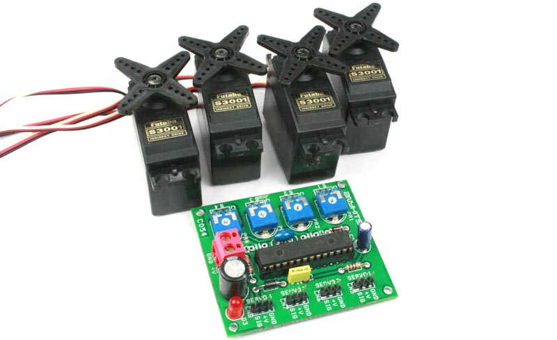
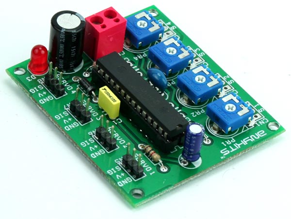
This PIC microcontroller based RC driver is able to control 4 RC Servo by on board independent 4 potentiometer , 4X3PIN header for RC servo interface, screw terminal for supply input, on board power LED, optional 4X3PIN header connector for external potentiometer.
Features
- Microcontroller based design for greater flexibility and ease of control
- Individual servo controlled via onboard preset or external potentiometer
- Power supply input 5 VDC
- Screw terminal connector for easy connection of the input power supply
- Protection diode for reverse supply
- Berg connector for connection of Servos
- Power-On LED indicator
- Four mounting holes of 3.2 mm each
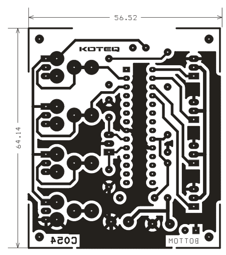
- PCB dimensions 56.52mm x 64.14 mm
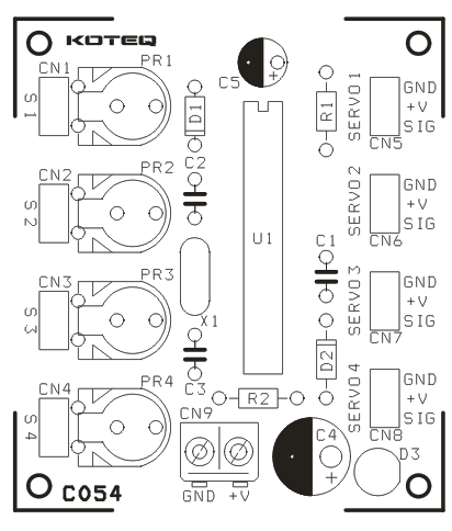
Connections
- CN1 Connector : External Potentiometer Connection for Servo 1
- CN2 Connector : External Potentiometer Connection for Servo 2
- CN3 Connector : External Potentiometer Connection for Servo 3
- CN4 Connector : External Potentiometer Connection for Servo 4
- CN5 Connector : Connection for Servo 1
- CN6 Connector : Connection for Servo 2
- CN7 Connector : Connection for Servo 3
- CN8 Connector : Connection for Servo 4
- CN9 Connector : Power Supply Input 5 VDC
- D3 LED : Power-On LED indicator
Note: CN1, CN2, CN3, CN4 optional connector to connect external potentiometer (Omit on board preset for external potentiometer)
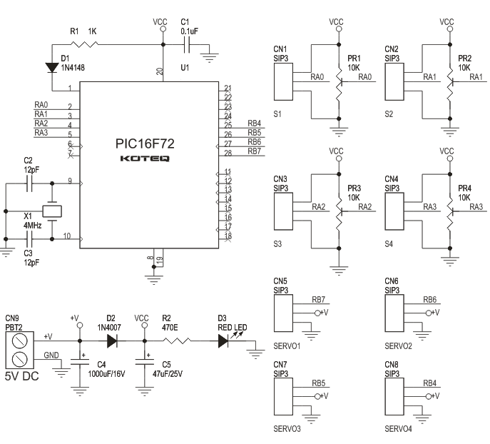
Schematic
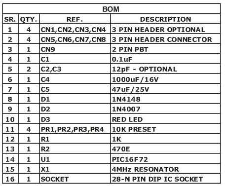
Parts List
Photos
Please follow and like us:
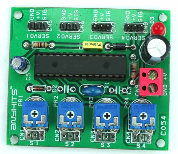
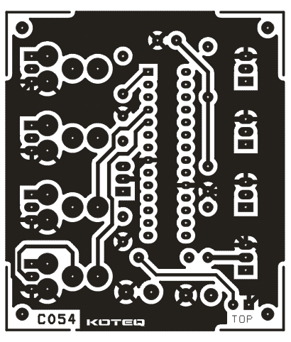
PCB


hi. im using sg90 with this project. its said that sg90 has 180 degrees turning angle but in this board the motor cant turn even 90 degrees. what is the problem?
This servo motor can move to +/- 90 degrees in each direction. Do you have an oscilloscope to test the signal produced? Position “0” (1.5 ms pulse) is middle, “90” (~2ms pulse) is middle, is all the way to the right, “-90” (~1ms pulse) is all the way to the left.
wrote below code. i see the same result in proteus (also achieved same oscilloscope view) but in real circuit servos turning randomly. any ideas about 16f873 setup?
TRISA=%111111
TRISB=%00000000
TRISC=0
DEFINE ADC_BITS 10
DEFINE ADC_CLOCK 3
DEFINE ADC_SAMPLEUS 1
‘——————————————————————————-
ADCON1=%10000000
‘——————————————————————————-
S0 var word
S1 VAR WORD
S2 VAR WORD
S3 VAR WORD
S0=0
S1=0
S2=0
S3=0
ANALOG:
ADCIN 0,S0
ADCIN 1,S1
ADCIN 2,S2
ADCIN 3,S3
PORTB.4=1
PAUSEUS (975+S0)
PORTB.4=0
PAUSEUS 50
PORTB.5=1
PAUSEUS (975+S1)
PORTB.5=0
PAUSEUS 50
PORTB.6=1
PAUSEUS (975+S2)
PORTB.6=0
PAUSEUS 50
PORTB.7=1
PAUSEUS (975+S3)
PORTB.7=0
PAUSEUS 50
PAUSEUS (17000-(S0+S1+S2+S3))
GOTO ANALOG
end
ADC of 16f873 returns with 16 bit but i calculated code for 10 bit. so when i divide s0,s1,s2 and s3 with decimal 65 its ok now. but motors are vibrating a bit. code must not be as mine 🙂