
16 Channel RC Servo Driver with I2C Interface
- Rajkumar Sharma
- 91 Views
- easy
- Tested
- SKU: EL140867
- Quote Now
- 1 Likes

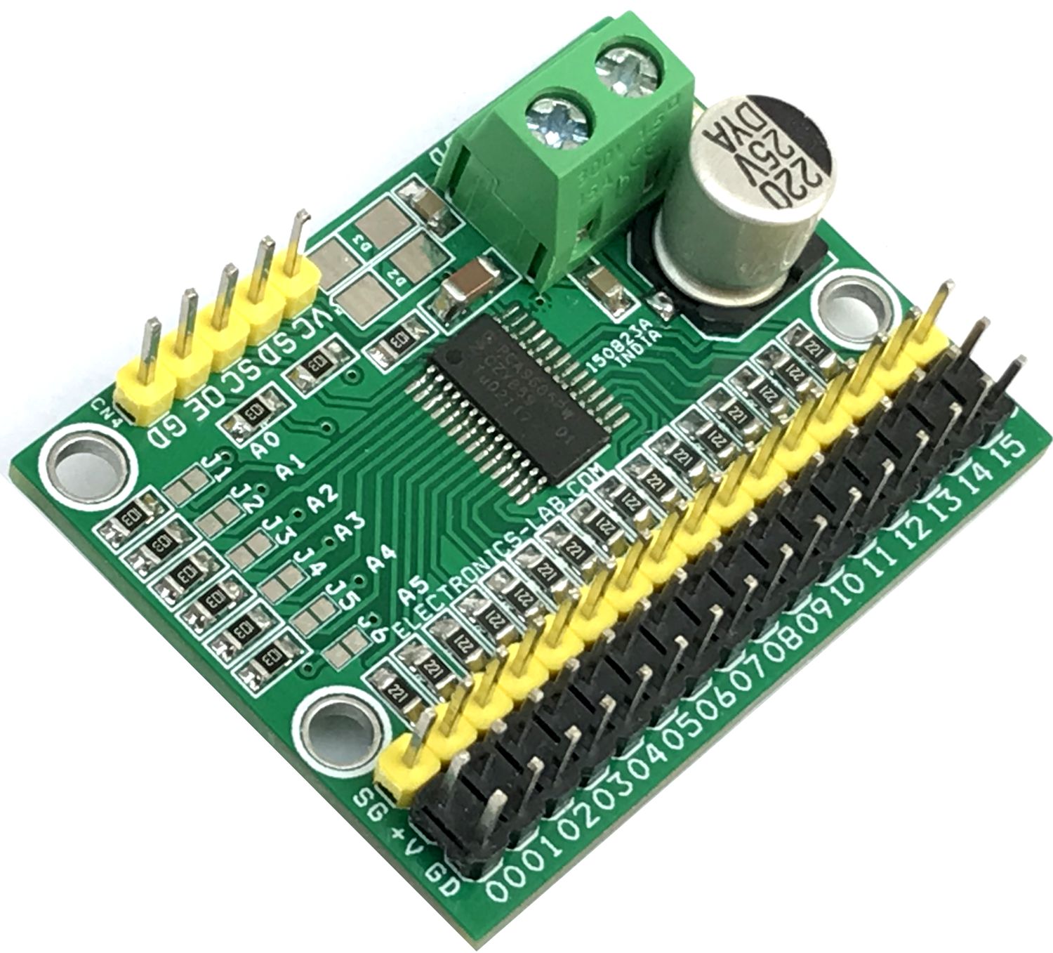
This is a 16-channel servo driver that can drive 16 x RC servos over I2C interface. The project is built using PCA9685 chip, a 16-channel PWM generator that can drive 16-channel servos simultaneously. The board can be connected to Arduino or another microcontroller. Driving robots, and animatronics puppets is easy with this board. The board works with 5VDC and a separate power supply connector is provided to power the RC servo with 6VDC. 6 x address Solder jumper is provided to set the board address, and this helps users to wire up 62 board on a single I2C line and drive up to 992 servos. The board also can be used for other applications that require 16-channel PWM signals. The frequency can be adjusted between 24 Hz to 1526 Hz and the duty cycle ranges from 0 to 100%.
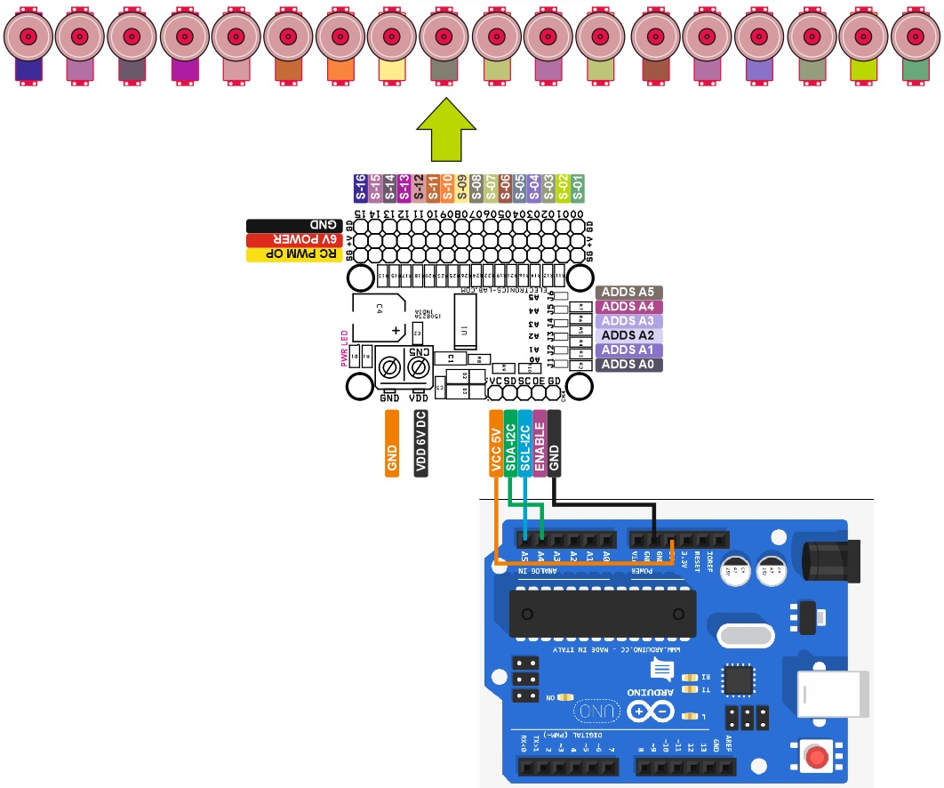
It is important to use a high current power supply that should be able to power the total load of 16 servos and use a C4 = 1000uF/10V capacitor. You can also download the Arduino code to test the board. The test is done with Arduino UNO. The following Arduino pins are used to perform the test, refer to the connection diagram for the connection between Arduino Uno and the PWM board.
Arduino Uno Connections
- Pin 1 VCC = 5V DC
- Pin 2 SDA = Arduino Uno Analog A4
- Pin 3 SCL = Arduino Uno Analog A5
- Pin 4 OE (Output Enable), OE=High All outputs are Disabled, OE=Low = All outputs are Enabled
- Arduino Library: https://github.com/adafruit/Adafruit-PWM-Servo-Driver-Library
Features
- Power Supply RC Servo 6V DC (VDD)
- Power Supply Chip/Logic 5V DC (VCC)
- 3 Pin x 16 Header Connector for 16 RC Servo
- Screw Terminals for RC Servo (6V DC) RC Servo Power Supply
- 5 Pin Header Connector for I2C Interface and VCC Power
- On Board Power LED
- 6 Solder Jumper to Set the I2C Address
- 66 Board can run over a single I2C Bus which can output 992 Channels
- Adjustable Frequency 24 Hz to 1526 Hz
- Adjustable Duty Cycle 0 to 100%
- Configurable Push-pull or Open-drain Output
- Output Enable Pin to Disable All the Outputs
- 4 x 3mm Mounting Holes
- PCB Dimensions 44.13 x 34.45mm
Applications
- Animatronics
- Puppetry
- Multi-Servo Based Robots
- Hexapod Robot
- Servo-Based Robotics Arm
- Automation
Connections and Other Details
- Jumper J1 = Address A0
- Jumper J1 = Address A1
- Jumper J1 = Address A2
- Jumper J1 = Address A3
- Jumper J1 = Address A4
- Jumper J1 = Address A5
- CN1 1 x16Pin = PWM 0-15
- CN2 1x16Pin = VDD=6V
- CN3 1x16Pin = GND
- CN4: Pin 1 VCC(5VDC), Pin 2 = SDA, Pin 3 = SCL, Pin 4 = OE(Enable), Pin 5 = GND
- CN5: Pin 1 VDD(6VDC) for Servo, Pin 2 GND
- D1 Power LED
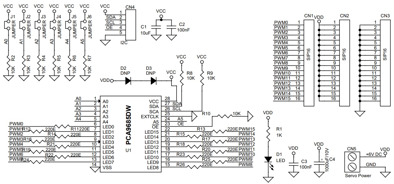
Schematic
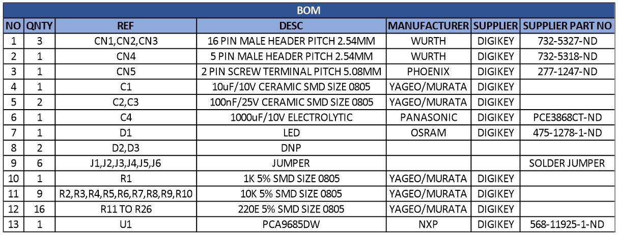
Parts List
| NO | QNTY | REF | DESC | MANUFACTURER | SUPPLIER | SUPPLIER PART NO |
|---|---|---|---|---|---|---|
| 1 | 3 | CN1,CN2,CN3 | 16 PIN MALE HEADER PITCH 2.54MM | WURTH | DIGIKEY | 732-5327-ND |
| 2 | 1 | CN4 | 5 PIN MALE HEADER PITCH 2.54MM | WURTH | DIGIKEY | 732-5318-ND |
| 3 | 1 | CN5 | 2 PIN SCREW TERMINAL PITCH 5.08MM | PHOENIX | DIGIKEY | 277-1247-ND |
| 4 | 1 | C1 | 10uF/10V CERAMIC SMD SIZE 0805 | YAGEO/MURATA | DIGIKEY | |
| 5 | 2 | C2,C3 | 100nF/25V CERAMIC SMD SIZE 0805 | YAGEO/MURATA | DIGIKEY | |
| 6 | 1 | C4 | 1000uF/10V ELECTROLYTIC | PANASONIC | DIGIKEY | PCE3868CT-ND |
| 7 | 1 | D1 | LED | OSRAM | DIGIKEY | 475-1278-1-ND |
| 8 | 2 | D2,D3 | DNP | |||
| 9 | 6 | J1,J2,J3,J4,J5,J6 | JUMPER | SOLDER JUMPER | ||
| 10 | 1 | R1 | 1K 5% SMD SIZE 0805 | YAGEO/MURATA | DIGIKEY | |
| 11 | 9 | R2,R3,R4,R5,R6,R7,R8,R9,R10 | 10K 5% SMD SIZE 0805 | YAGEO/MURATA | DIGIKEY | |
| 12 | 16 | R11 TO R26 | 220E 5% SMD SIZE 0805 | YAGEO/MURATA | DIGIKEY | |
| 13 | 1 | U1 | PCA9685DW | NXP | DIGIKEY | 568-11925-1-ND |
Connections
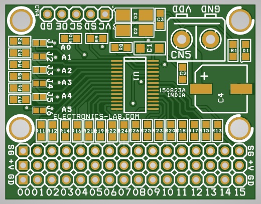
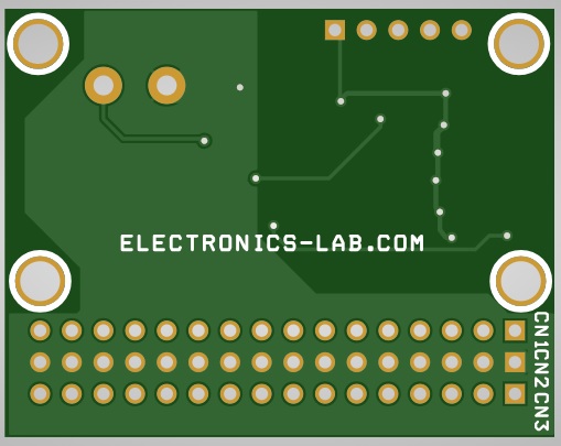
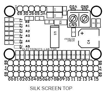
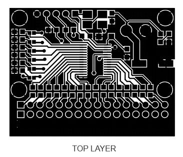
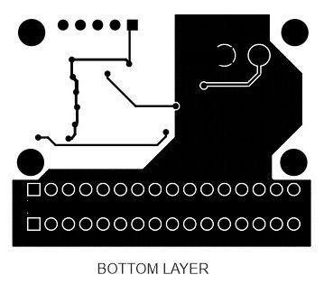
Gerber View
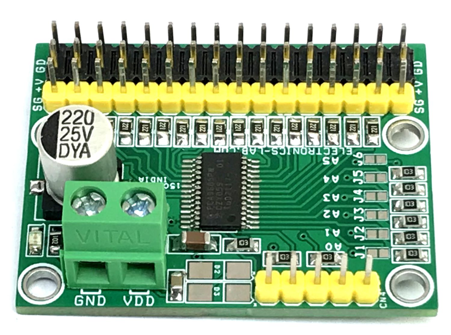
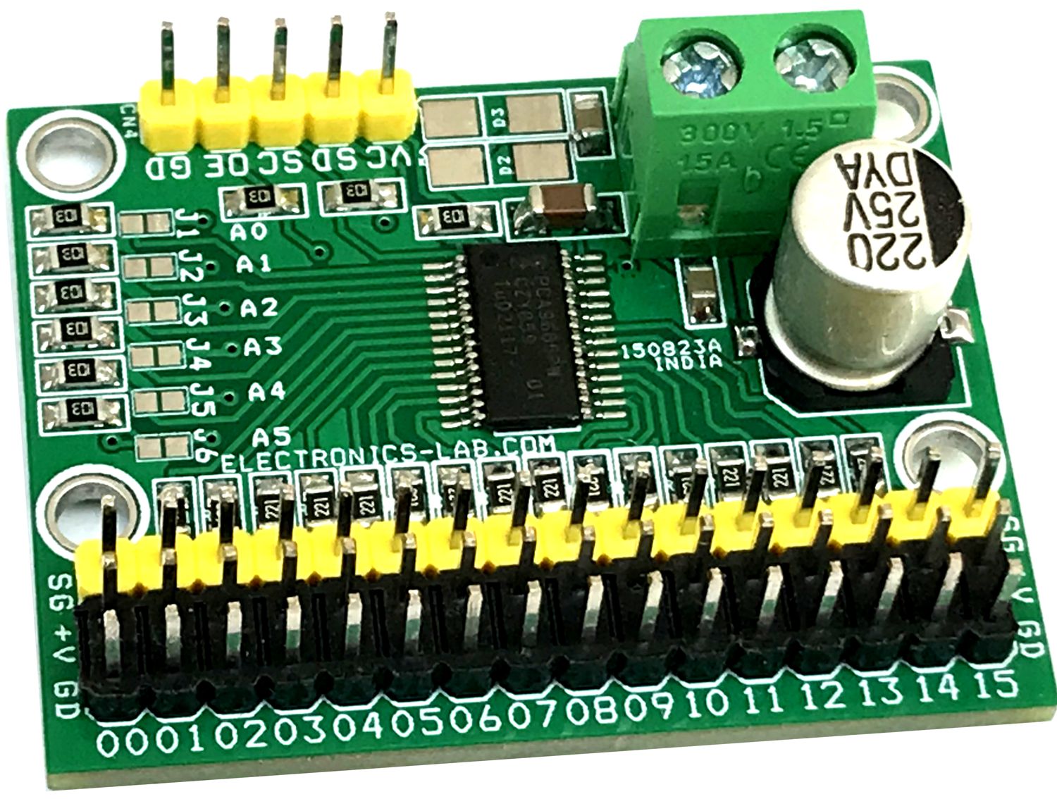
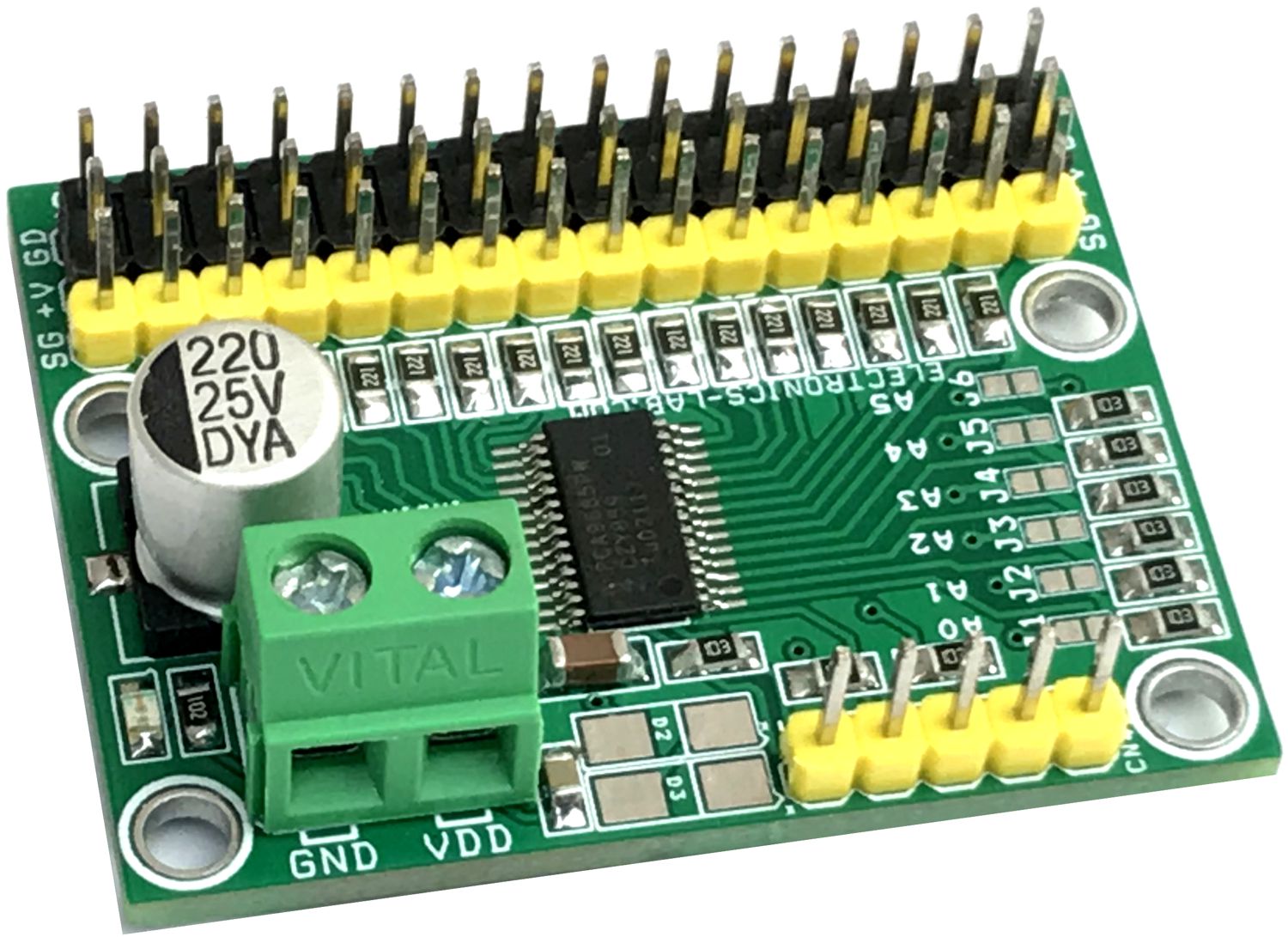
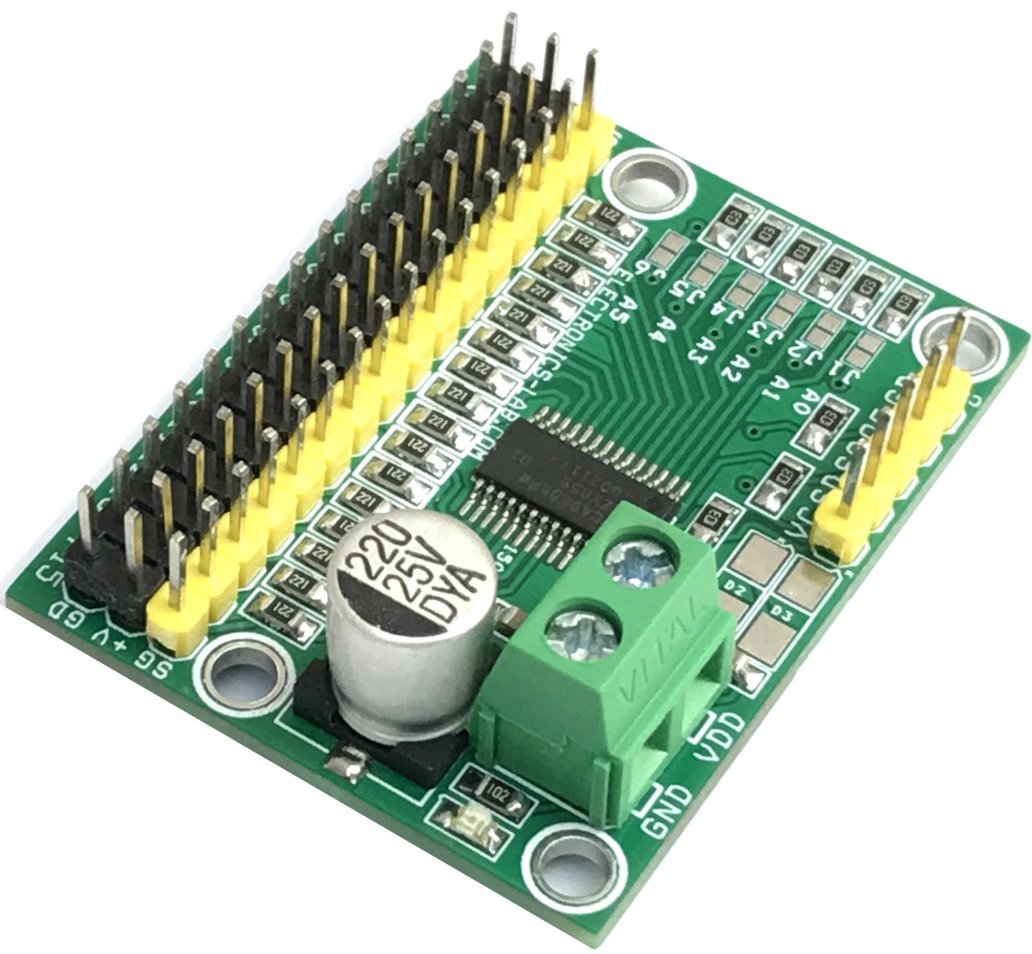
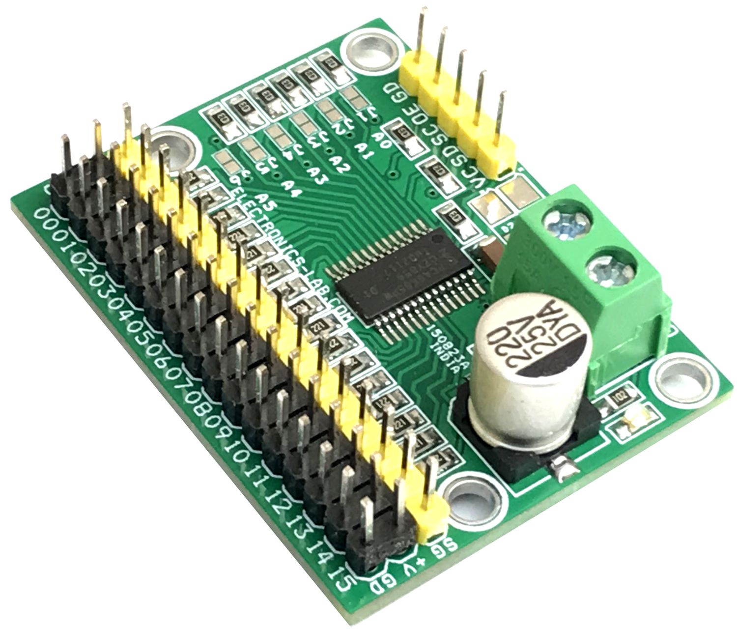
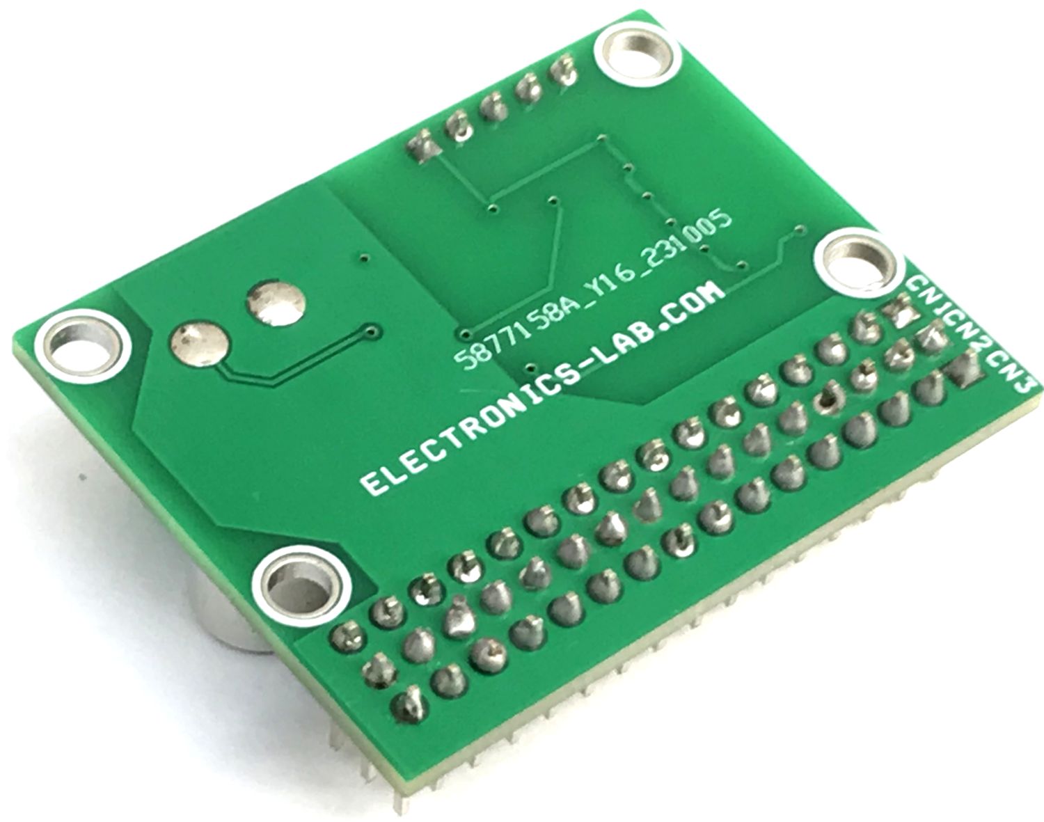
Photos
Videos
PCA9685 Datasheet
PCB