

Arduino (Atmega328p) on a Breadboard
- Nick Koumaris
- https://educ8s.tv
- info@educ8s.tv
- 34.080 Views
- moderate
- Tested
- 0 Likes

Introduction
Hi guys, for today’s tutorial, we will be building an Arduino on a breadboard. The Arduino on breadboard is basically a bare bones arduino, featuring only the micro-controller as the major component, without all the other parts that makes up the Arduino, like the USB port, the on-board serial to usb converter, voltage regulators, etc, most of which are sometimes not needed in a project after programming has been done.
While they look similar, the difference between the ordinary atmeg328p microcontroller based circuit and the arduino on breadboard is the fact that, the microcontroller used for the Arduino on breadboard always carries the arduino bootloader which allows it to be programmed using the arduino IDE. This is not the case with the ordinary atmeg328p microcontroller system as the microcontroller can’t be programmed using the Arduino IDE.
This project is very easy and shouldn’t take a lot of time to implement, but before we proceed to the tutorial, its important to explore some of the benefits and reasons for this project, especially when we could get a cheap “alternative” in the Arduino pro mini for less than $2, if size was the only benefit.
Some benefits of the Arduino on Breadboard are listed below with the most important one for me being the second one as optimizing power for devices is very important in design.
- Working with the Atmega328p on a breadboard will give a deeper understanding of how the Arduino hardware works.
- The second benefit is the low power consumption of this project, compared to all other types of Arduino including the pro mini, this consumes far less amount of power in standby mode. Reason for this is obviously the removal of all the other peripherals that comes with other arduino board.
- Its easier to scale an electronic prototype implemented using the arduino on breadboard as you are privy to every detail.
Components Required
The following components will be needed to build this project;
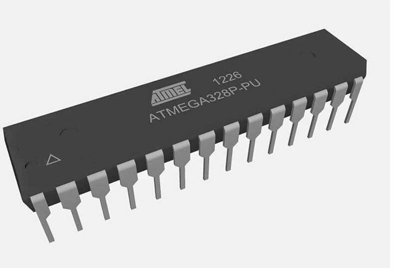
- Atmega 328 with Arduino Bootloader
- 2x 22pF capacitors
- 1x 100nF capacitors
- A USB to serial converter module
- A resistor
- LED
- AA battery holder
- Small Breadboard
- Wires
- 16mHz Crystal Oscillator
- Multimeter Mastech 8268
While buying the atmega328p, its important to ensure that the one being bought, has the Arduino bootloader on it as this procedure will not work for the atmega chip without the Arduino bootloader.
Schematics
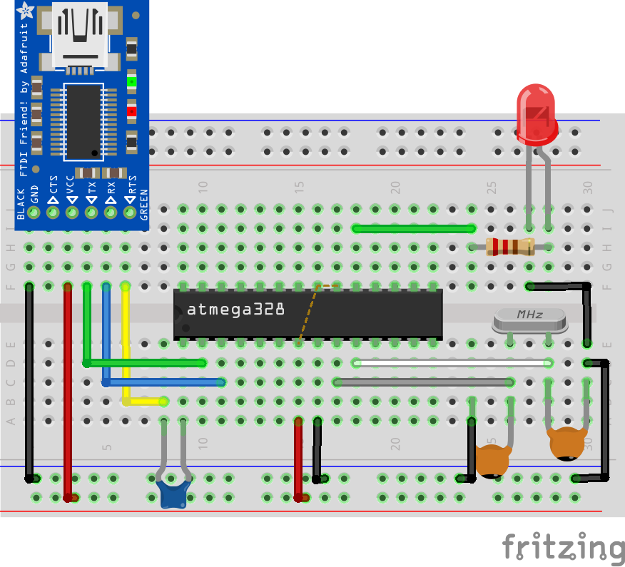
Connect the components of the Arduino on breadboard as shown in the schematic below.
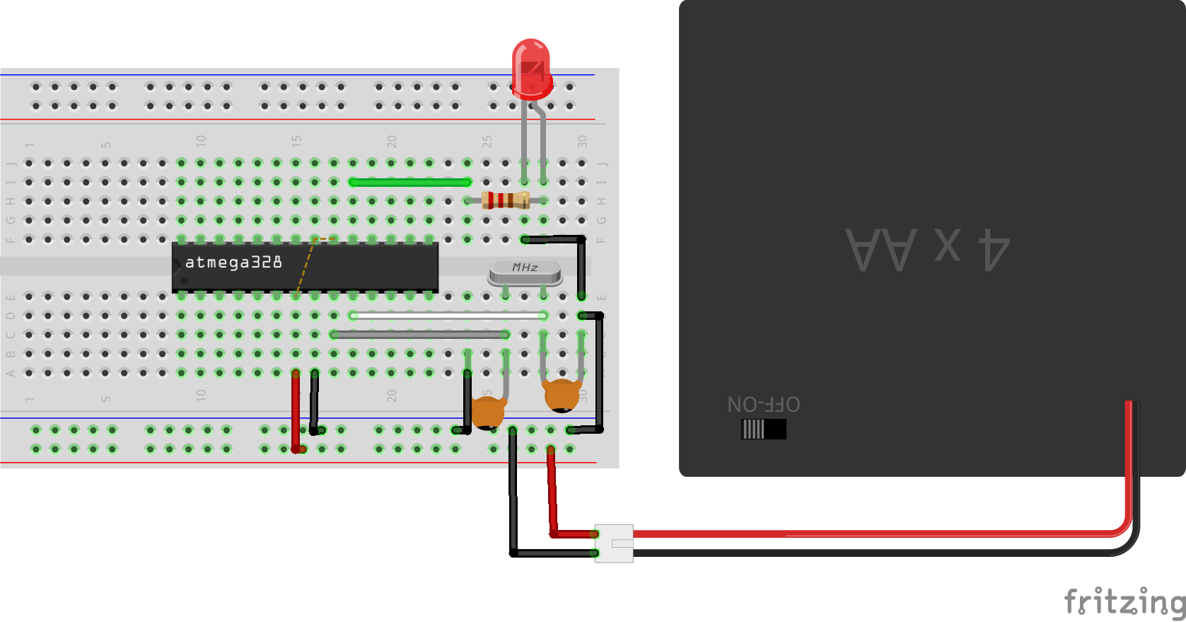
To make it easy to connect the components to the microcontroller, A sticker which translates the pins of the microcontroller to the equivalent pin on the Arduino is pasted on top of the microcontroller. This sticker is included in the zip file attached at the end of this tutorial and can be used to make the connections easy for you.

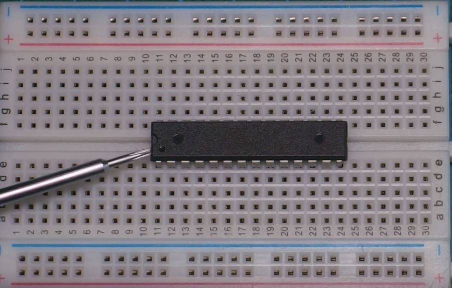
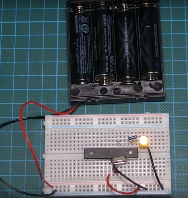
While plugging the microcontroller to the breadboard, take note of the notch at the top left which signifies the first pin (RST) of the microcontroller. Numbering of the microcontroller’s pin should start from there to prevent connecting the components wrongly.
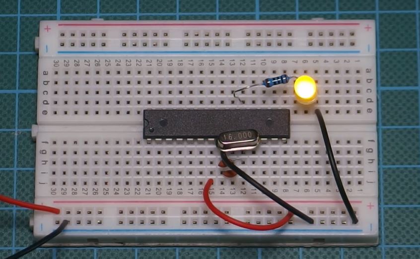
With the circuit and power connected, you should see the led start blinking.
It should be noted that the maximum voltage which should be applied to the VCC pin of the atmeg328p microcontroller is 6v and this should be avoided, as the advisable working voltage is between 3.3V and 5.5V.
Programming the Breadboard Arduino
Once the component setup is done, the next thing is programming the arduino on breadboard to run our desired code/firmware. The flashing of the LED that we saw from the last section after the setup was powered was due to the blink led code that comes with the Arduino bootloader. To program the Arduino on breadboard and flash it with your own code, we will need to connect the USB to Serial Converter module to the Arduino on breadboard.
USB to serial adapters generally connect a serial device to the computer via USB ports. It gives the Arduino IDE the communication path needed to flash the microcontroller with the written Arduino code. On boards like the Arduino UNO, the communication between the microcontroller and the USB port is achieved by the actions of the ATMEGA8u2 chip which behaves as the bridge between the USB port and the microcontroller on the board.
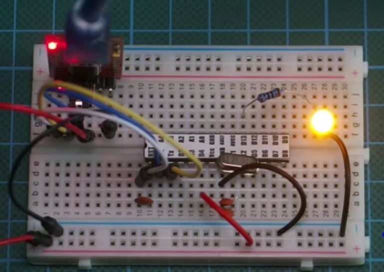
Connect the USB to serial converter module to the Arduino on breadboard circuit as shown in the image below.
USB to Serial – Arduino on Breadboard
Rx - Tx
Tx - Rx
Vcc - Vcc
GND - GND
RTS/DTR - RST(Via 100nf Capacitor)
With the connection all done, connect the setup to your computer and open the Arduino IDE.
To upload code to the Arduino on breadboard, after writing your code (For the purpose of this tutorial, we are modifying the blink example), go to the tools section and select board type. For the arduino on breadboard, the matching board type is “Arduino Duemilanove or Nano w/ ATmega328“, select this alongside the matching com port and you are ready to upload to the microcontroller as normal.
Code
This section exists just in case you are interested in our code. As mentioned earlier, its a modified version of the Arduino blink program but features the Lowpower.h Arduino library.
The arduino low power library is a lightweight power management library for the arduino which allows the arduino peripherals like the ADC etc be turned off to conserve power. The library has different functions with different operation modes and may be worth exploring. it can be downloaded from here.
The first thing we do in the code imports the low power library which allows us to do everything that has been said about it in the previous paragraph, after which we proceed to the void setup where we do just one thing; set the pin 13 as an output.
//written by Nick Koumaris
//info@educ8s.tv
//educ8s.tv

#include "LowPower.h"

void setup()
{
  pinMode(13, OUTPUT);
}
Next is the void loop where the real action happens, we instruct the microcontroller via the lowpower.powerdown() command to go into sleep mode, for 8s, turning off the ADC and other peripherals.
void loop()
{
    // Enter power down state for 8 s with ADC and BOD module disabled
    LowPower.powerDown(SLEEP_8S, ADC_OFF, BOD_OFF);
As soon as the microcontroller wakes up from the sleep, it then writes pin 13 high, for 1s and then turn it back low.
digitalWrite(13, HIGH);   // turn the LED on (HIGH is the voltage level)
  delay(1000);              // wait for a second
  digitalWrite(13, LOW);    // turn the LED off by making the voltage LOW
  delay(1000);
The full code is available below and in the zip file attached at the end of the post.
// **** INCLUDES *****
#include "LowPower.h"

void setup()
{
  pinMode(13, OUTPUT);
}

void loop()
{
    // Enter power down state for 8 s with ADC and BOD module disabled
    LowPower.powerDown(SLEEP_8S, ADC_OFF, BOD_OFF);

  digitalWrite(13, HIGH);   // turn the LED on (HIGH is the voltage level)
  delay(1000);              // wait for a second
  digitalWrite(13, LOW);    // turn the LED off by making the voltage LOW
  delay(1000);
}
After uploading to your Arduino on a breadboard, you should see the LED come on for one second and go off for the next 8s.
Works right? Yea, here is a picture of ours too working.
So now you can proceed and build several other cool projects using the Arduino on breadboard.
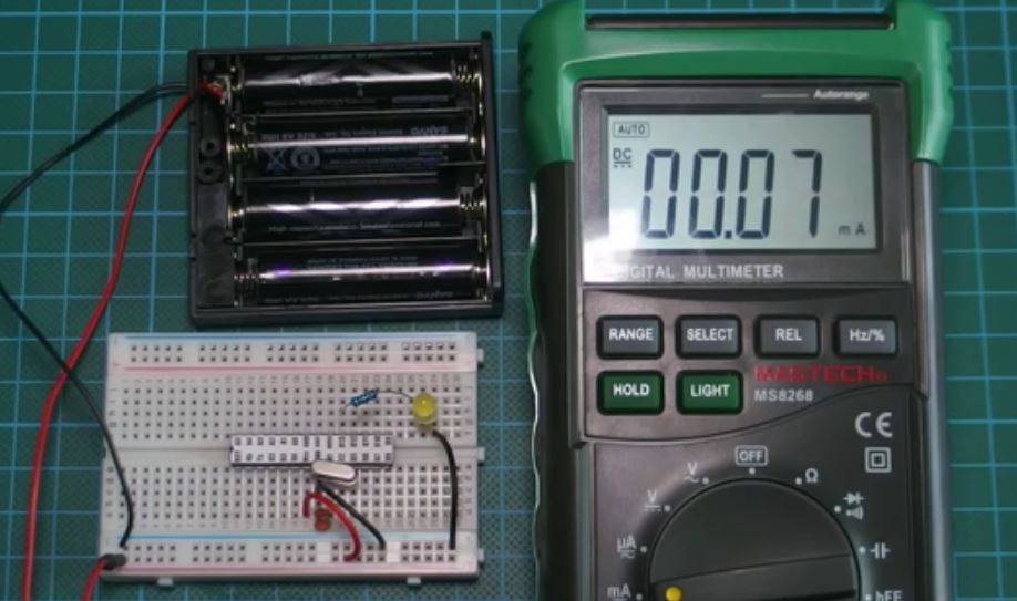
As a proof of the low power consumption rate of the microcontroller when in idle mode, we used the maestech meter to measure the current consumption and got 0.07mA in idle mode. This is far less than any of the Arduino boards with Arduino pro mini consuming around 3mA and Uno, 30mA in Idle Mode. This shows that you can have an Arduino project like a weather station for example, that could last for years running on batteries and this increases the potential of what you can do with the Arduino platform drastically.
That’s it for this tutorial guys, don’t forget to leave questions, and comments, in the comments section of the tutorial.
Till next time, Keep Building!
The youtube video for this tutorial is available via the attached link, here.


Hi, what board do you select in the arduino IDE?
Thanks, cool web page!
g
Arduino Duemilanove or Nano w/ ATmega328