

Using the SG90 Servo Motor With an Arduino
- Nick Koumaris
- http://educ8s.tv
- info@educ8s.tv
- 104.969 Views
- easy
- Tested
- 2 Likes

Hi guys, today, I will show you how to use a servo motor with an Arduino. This tutorial is ideal for beginners because it is easy and it gives them the foundation to build interesting projects like robots for which servos are commonly used.
Servo motors are high torque motors which are commonly used in robotics and several other applications due to the fact that it’s easy to control their rotation. Servo motors have a geared output shaft which can be electrically controlled to turn one (1) degree at a time. For the sake of control, unlike normal DC motors, servo motors usually have an additional pin asides the two power pins (Vcc and GND) which is the signal pin. The signal pin is used to control the servo motor, turning its shaft to any desired angle.
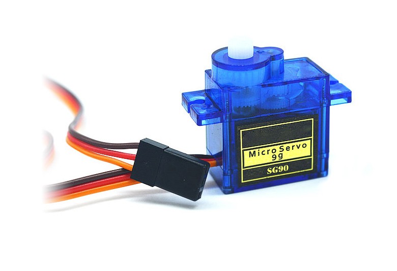
For this tutorial, we will be using the popular SG90 servo motor and our goal will be to rotate the servo motor from one end to the other.
Servo’s have high current requirement so when using more than one servo motor with the Arduino, it is important to connect their power connections to an external power supply as the Arduino may not be able to source the current needed for the servo. Since we will be using just one servo in this tutorial its fine to power it with an Arduino.
Required Components
The following components are required to build this project:
- SG90 Servo
- Cheap Arduino Uno
- Wires
- Breadboard
Each of these components can be bought via the link attached to them.
Schematics
The schematics for this project is quite simple as we will be connecting just the servo motor to the Arduino.
Servo motors generally have three pins/wires, this includes the VCC, GND, and the Signal pin. The Signal pin is the one used to feed the control signal from the microcontroller to the servo, to get the servo rotate to a particular angle.
Connect the Servo to the Arduino as shown in the schematics below.
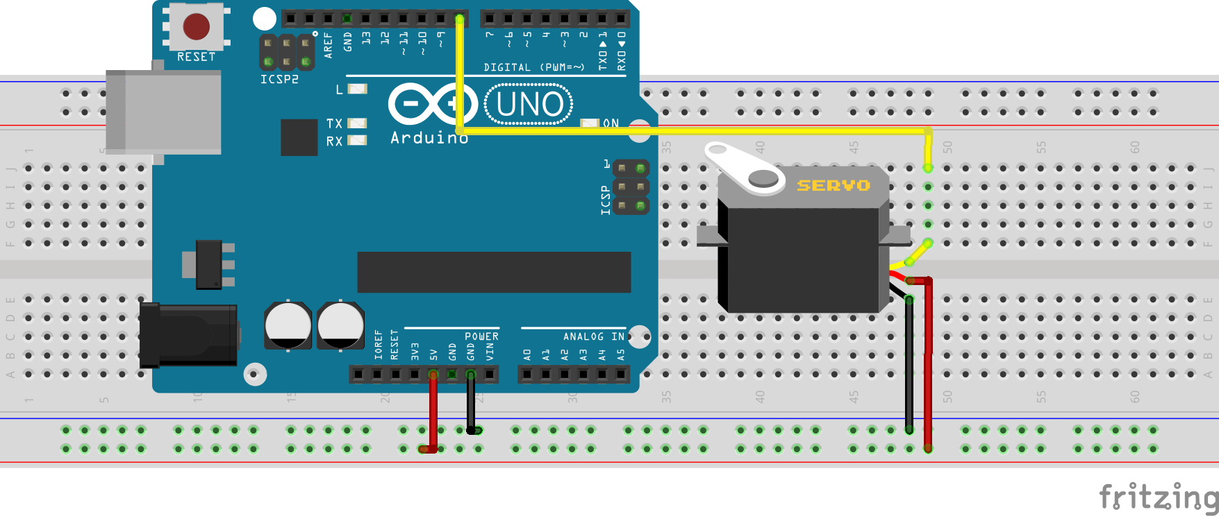
For emphasis, the connection is further described below.
SG90 Servo – Arduino
VCC(Red wire) - 5V
SIG(yellow/orange) - D8
GND(Black/Brown) - GND
The signal pin was connected to the digital pin 8 of the Arduino because it is a PWM pin. Servo directions are sent from the microcontroller to the servo motor as PWM pulses.
With the connection all done, we can now proceed to write the code for the project.
Code
The code for this project is quite easy thanks to the very comprehensive and concise servo.h library developed by the Arduino team to facilitate the use of servo motors in Arduino projects. The library makes it easy to turn the servo at different angles using a single command. The library comes pre-installed in the Arduino IDE removing the need for us to download and install.
We start the code for the project by including the libraries that we will use which in this case is the servo.h library.
#include <Servo.h>
Next, we create an object of the library, to be used as a reference for controlling our servo motor throughout the code.
Servo servo;
With this done, we proceed to the void setup() function. we start the function by attaching the servo object created to pin D8 of the microcontroller, after which we center the servo, turning it to zero degrees.
void setup() {
  servo.attach(8);
  servo.write(angle);
}
With that done, we are ready to move the servo in any direction we desire, and we will be doing this under the void loop function. Thanks, to the servo.h library all we need to do, to rotate the servo to an angle we desire, is to pass the desired angle as an argument into the servo.write() function. To demonstrate this, a for-loop was used to turn the servos at several angles in one direction and another loop was used to turn the servo back to where it started.
void loop()
{
 // scan from 0 to 180 degrees
  for(angle = 10; angle < 180; angle++)
  {
    servo.write(angle);
    delay(15);
  }
  // now scan back from 180 to 0 degrees
  for(angle = 180; angle > 10; angle--)
  {
    servo.write(angle);
    delay(15);
  }
}
The complete code for the project is available below and can be downloaded from the download section at the end of the tutorial.
#include <Servo.h>

Servo servo;
int angle = 10;

void setup() {
  servo.attach(8);
  servo.write(angle);
}


void loop()
{
 // scan from 0 to 180 degrees
  for(angle = 10; angle < 180; angle++)
  {
    servo.write(angle);
    delay(15);
  }
  // now scan back from 180 to 0 degrees
  for(angle = 180; angle > 10; angle--)
  {
    servo.write(angle);
    delay(15);
  }
}
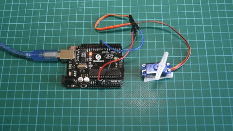
Demo
Copy the code above and upload to your Arduino and servo motor setup, after a few time, you should see the servo motor start turning as shown in the gif below.
That’s it for this tutorial guys, the code above can be expanded in several ways for use in different projects involving servo motors, what cool thing will you be building with the servo motor? feel free to share via the comment section.
The video tutorial for this project can be watched on youtube.


In your article on page https://www.electronics-lab.com/project/using-sg90-servo-motor-arduino/ is listed at “REQUIRED COMPONENTS”: Distance Sensor.
But this sensor is not connected and how it works.
Hi Pierre, Sorry about that, this was meant to be the first part of a tutorial that uses the other components mentioned up there. Will correct ASAP. However, we have a tutorial on the use of the distance sensor (HC-SR04) located here ( https://www.electronics-lab.com/project/arduino-distance-meter-ultrasonic-sensor-hc-sr04-nokia-5110-lcd-display/ ).
Hi Emmanuel,
The -distance-meter-ultrasonic-sensor is a verry good thing, but what I need is Is not really that.
Actually, it is the combination of the servo and sensor (HC-SR04). may also IR, PIR or Phototransistor.
The intention is if the sensor is activated to start the servo, when the sensor is no longer active the servo goes back to its original place and stops.
The distance that the servo in my case should do is 7200 full throttle round trip (± 337 cm).
The servo separately works for this time but but non-stop.
Hi, thanks for the share, just wanted to remind that Pin 8 is not a PWM pin.
I’dont understand that part. In every site I look (but this) they say you need pwm pin. But It works even if you use pin 2 or 8 for example, and they are not pwm.