

IR remote extender
- Michail Papadimitriou
- 69.178 Views
- moderate
- Tested
- SKU: EL36019
- Quote Now
- 0 Likes

This project describes how to build an IR remote control extender / repeater to control your electronic appliances from a remote location.
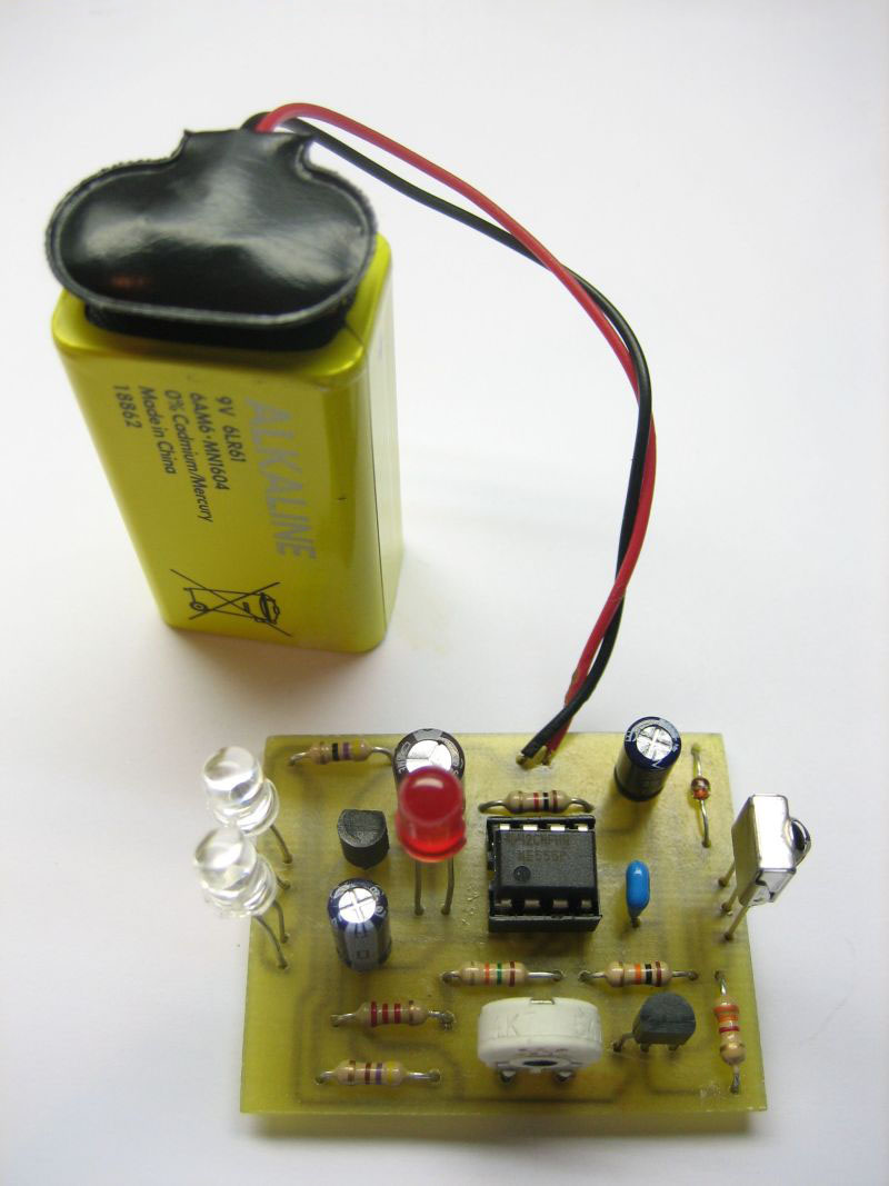
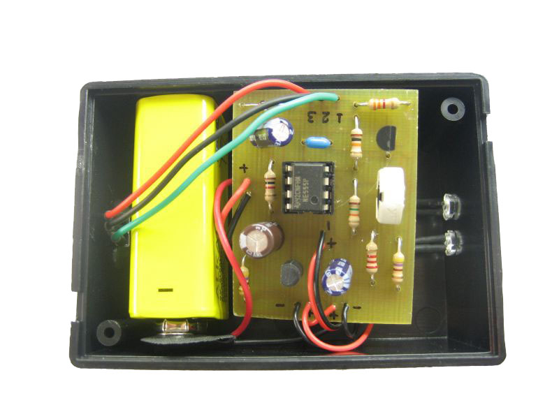
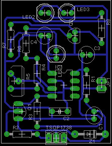
An IR detector module receives IR signal from remote control and two IR leds are re-emitting the signal to the appliance. You can place the IR emitting leds close to the device you would like to control using some wire and keep main unit close to remote control location. In the image at the left LEDs are soldered on the board. The circuit consists of three main parts, the IR receiver module, a 555 timer configured as an oscillator and the output / emitter stage. We will describe circuit operation below.
Circuit is designed by Andy Collinson and can be found here:http://www.zen22142.zen.co.uk
IR Signal
The IR signal emitted from a remote control caries the information needed to control the appliance. This signal consists of pulses that code 0 and 1 bits, instructing the appliance to do a certain operation. One of the most common protocols used to code the IR signal is Philips – RC5 protocol. The signal consists of two parts, the control pulses and the carrier wave as seen in the image below.
A common frequency used for the carrier is 38KHz and control pulses frequency is in the range of 1-3KHz. The carrier signal is modulated by the control pulses and the resulting signal is emitted by remote in IR band of the electromagnetic spectrum. IR band is invisible to the human eye. You can see if an IR led is emitting light or not using a camera. Point the camera to the led and you will see that light comes off.
Circuit description
IR signal is received by TSOP1738. TSOP1738 is an infrared receiver at 38KHz. At the output of the infrared receiver, we get a demodulated signal that means we get the low-frequency control pulses. The infrared receiver is powered from C1, R1, and Z1 that forms a 5V power supply. With no signal received, infrared detector output is high and Q1 is on, so pin 4 of IC is LOW and the 555 timer is in the reset state. Q1 also acts as a level shifter that converts 5V signal of TSOP1738 to 9V signal for IC1.
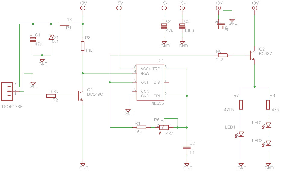
When HIGH control pulses are appearing on TSOP1738 output then timer 555 (which is configured as an oscillator) starts to oscillate at a preset frequency, for the duration of each data pulse. That means that at pin 3 we get a signal that is similar to the modulated source signal. It has a carrier component and a control pulses component. The oscillating frequency of 555 timer is set by R4 and C2 and pulse period is given by:
T = 1,4 R4 C2
Trimmer R5 is used to fine-tune oscillating frequency at 38KHz. That’s equal to the carrier frequency.
The output stage is formed from R6, Q2, one red LED, two IR LEDs, and two current limiting resistors R7 and R8. Q2 is connected as a voltage follower, which means when the base of Q2 is HIGH transistor is ON allowing current to flow through LEDs. LED current is set by R7 and R8 according to the following formula:
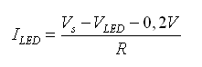
So IR LEDs are emitting a signal that is similar to the signal received by TSOP1738, which means it repeats the signal received at higher infrared radiation intensity. The red LED is used as an optical indicator of the output signal. The circuit can be powered from a 9V battery.
Parts List
| Part | Value |
|---|---|
| R1 | 1k |
| R2 | 3k3 |
| R3 | 10k |
| R4 | 15k |
| R5 | 4k7 trimmer |
| R6 | 2k2 |
| R7 | 470R |
| R8 | 47R - 1/2W |
| C1 | 47uF - 16V |
| C2 | 1n - polyester |
| C3 | 100uF - 16V |
| C4 | 47uF - 16V |
| Z1 | 5V1 zener |
| Q1 | BC549C |
| Q2 | BC337 |
| IC1 | NE555 |
| LED1 | red LED |
| LED2-3 | IR LED |
| IR receiver | TSOP138 or IR38DM |
Testing
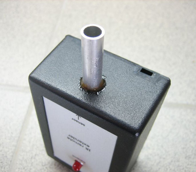
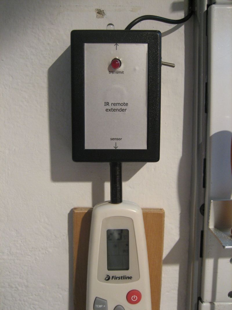
Before powering the circuit, remove IR LEDs. With no input red LED should be off. Now press a button on a remote control, red led should flicker. If that’s the case then your circuit should be working ok. Install IR LEDs. We found during testing that IR signal emitted from remote and IR signal emitted from circuit are interfering each other and that’s make receiving device not to react on receiving the signal, this happens when IR from remote and IR from circuit’s LEDs are on the same room. To solve that we must isolate the IR beam of remote control. To do that we used a thin pipe in front of infrared sensor as seen in photo below, so that the beam emitted from remote hits the sensor directly. Another solution to this would be to put the emitting LEDs on a different room.
Installation
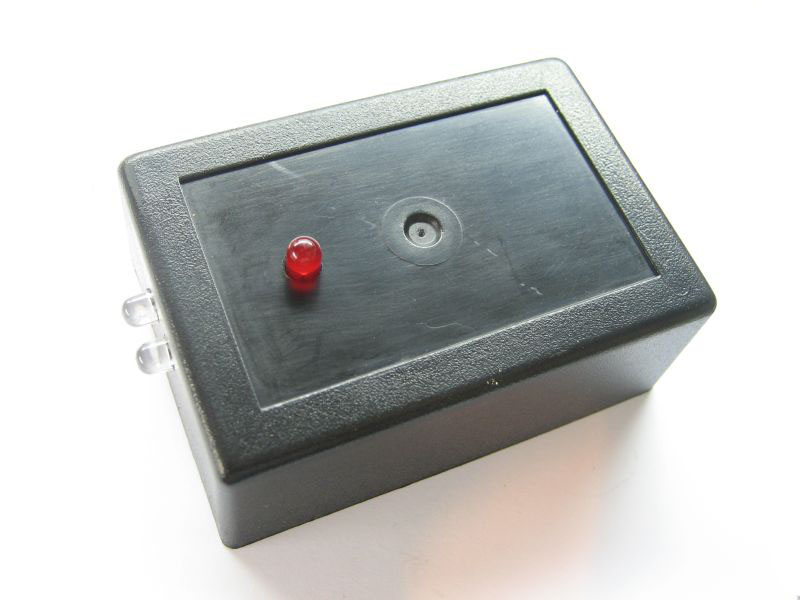
We installed the circuit on the wall the way you see on the photo below. You can see that remote control led is optically isolated from surround. You can also notice that one LED is remotely placed near the device we would like to control.
References
- http://www.epanorama.net/zen_schematics/Circuits/Interface/irext4.html
- http://www.zen22142.zen.co.uk/Circuits/Interface/irext4.htm
- http://www.sbprojects.com/knowledge/ir/rc5.htm
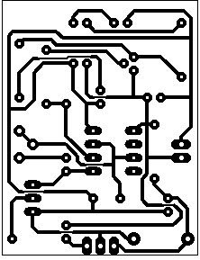
PCB


")

IR led doesn’t flashes in my cam .?whats the problem. ?circuitnot working but red led flashes with using remote control in front of circuit…? Plz guide
Why use a demodulating ir receiver like the tsop1738? Can’t you just use an ir sensitive receiver an amplifying transistor and the output led? That way you don’t have to demodulate the output greatly simplifying the circuit? Serious question.
Can one should made halmet based ignition of a vechile while using “IR” sensor?
Is this 100% working?
Yes, this is tested and working on my end.
Hey ive connected the circuit as follows but the leds work including the IR leds but on testing with a remote the red Led doesn’t blink
Can you verify that remote control is working and that there is a signal on the OUT pin of receiver.
i am quite sure that tsop1738 ir receiver module comes with demodulator inside so the output signal we get only the control signal. how can 555 output has carrier components?
555 IC creates the 38kHz carrier signal, means that based on the output of TSOP1738 it reconstructs the original signal emitted from IR remote and emit it again from the IR LEDs