

Logic Probe Plus
- Manel Navarro
- http://www.electronik.es
- 25.696 Views
- moderate
- Non tested
- 0 Likes

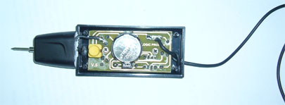
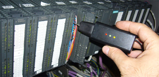
This project is based on a probe logic states, capable of measuring levels from TTL (5v) to state levels of PLC’s (24v). For this we have employed the use of the PIC 12F683 microcontroller, which by its nature is capable of operating at low voltages, in this case 3vcc, besides having analog inputs and internal oscillator.
The circuit is supplemented by an input stage which will adapt the signal to the levels between the microprocessor is able to work and another output stage that will visually show the state in which the point is measured.
The input stage to include a voltage divider between R3 D5 and D1, their role is to establish a fixed value (/ – 2.80) for the input of the microcontroller which means that is in a state of high impedance, ie without input signal. When we apply the input signal DATA IN this will vary the voltage drop at point H so that the reading as we discriminate if this is higher or lower than the reference voltage.
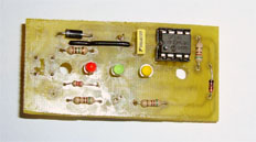
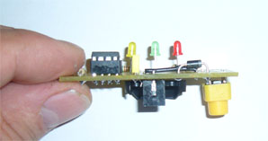
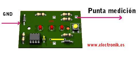
The output stage is made up 3 LED (yellow = high impedance, Green = Red = logic 1 and logic 0).
The program also has an internal timer to approximately 3 minutes between the microcontroller in sleep mode in which consumption will be minimal, to save the battery. And it will reactivate the program until you press the button, starting over allowing timing and take readings we require.
Focusing on the program of the microprocessor, this is configured to work with internal oscillation 4Mhz and configuring its pin so that analog reading take from point H by the GP1 pin, which is defined for a resolution of 10 bits, pin GP2 will also be defined as input and will be connected through a resistor (PULL UP) and a secondary switch to ground, which will be responsible for collecting the press that forced the interruption level change in GP2 While the interruption occurs loads a value (2000) as a timer to make a loop past work and this time will be placed the microcontroller in sleep mode.
The program is also complimented inizialización a function which shows the blinking leds, to argue that this in active process and that at the end of this sequence we can take appropriate measures.
The bulk of the program is effected by a loop of reading and comparing the reading which collects and compares GP1 activating the corresponding output.
In order to function alone is sufficient to connect the ground wire to any metal part of the chassis or failing to ground.
The code is open and available to anyone who want, just send an e-mail and ask.
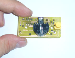
PCB


Thanks for this project. I am trying to find a low voltage probe to testguitar fx prdals. Have any resources for tha ??
Thanks
Manny
Can I have the full information for the project ike the full list of components need, I think its a nice one and I would like to try it.
hello friend I have all the components, I would like to point probrar logic, you could change for PIC12F629? from already thank you, greetings
I am sorry, the code is written for PIC12F683
Hi there. Could you send me the code please? Regards
Please email the author here: Electronik at Electronik.es
Hello there
I would want written code circuits. Thank you
Hi there. Could you send me the code please? Regards
Could you try to email the author electronik @ electronik.es ?
Hi.Please hex code daniel.mntean68@gmail.com
Hi.Please hex code quoccuong0279@gmail.com
hello sir, please send me hex code kumaranujkumar501@gmail.com